
Flame identification method of double-infrared-channel flame detector

A flame detector and flame recognition technology, applied in the direction of sensing radiation from gas/flame, fire alarm, electric radiation detector, etc., can solve the problem of not being able to monitor fire prevention areas all the time, flame detector false alarms, forest guardians, etc. Trouble and other issues

Active Publication Date: 2016-11-09
重庆英卡电子有限公司
View PDF5 Cites 12 Cited by
  • Summary
  • Abstract
  • Description
  • Claims
  • Application Information

AI Technical Summary

Problems solved by technology

Defects of forest rangers patrolling: First, people have limited energy and cannot monitor all fire prevention areas all the time; second, people themselves are also an uncontrollable factor
There are also problems in camera monitoring: first, the power consumption is too large, and at the same time, data transmission must be taken into account, so only wired power supply can be used, which leads to restrictions on the installation location; second, in order to ensure the monitoring field of view, it must be installed at the highest point in the monitoring area. It is difficult to monitor the early fire situation of surface fire and forest fire
[0003] The disadvantage of the infrared flame identification device in the prior art is that the reliability is poor, and it is easily disturbed by external environmental light sources such as surrounding lights, lightning, and sunlight. unnecessary trouble

Method used


Image

  • Flame identification method of double-infrared-channel flame detector
  • Flame identification method of double-infrared-channel flame detector
  • Flame identification method of double-infrared-channel flame detector

Examples


Embodiment Construction

[0059] The present invention will be described in further detail below in conjunction with the accompanying drawings and specific embodiments.

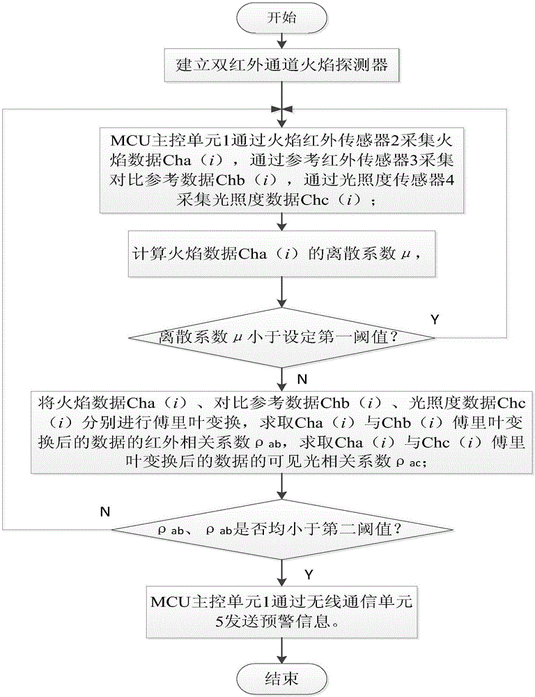
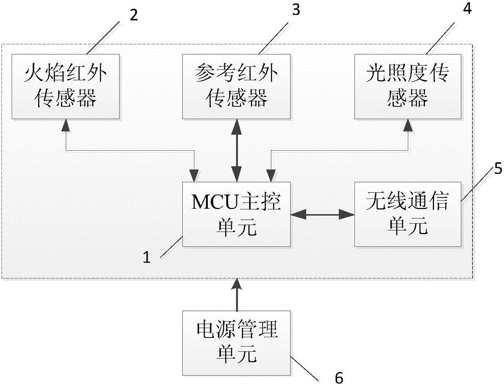
[0060] like figure 1 and figure 2 As shown, the present invention provides a kind of flame identification method of double infrared channel flame detector, is used for double infrared channel flame detector, and this flame identification method comprises the following steps:

[0061] Step a: first build a dual-infrared channel flame detector, the dual-infrared channel flame detector includes an MCU main control unit 1, the MCU main control unit 1 is provided with a first infrared channel end group, and the MCU main control unit 1 passes through the first infrared channel The channel end group is connected with a flame infrared sensor 2; the MCU main control unit 1 is also provided with a second infrared channel end group, and the MCU main control unit 1 is connected with a reference infrared sensor 3 through the second infrared chan...


PUM


Abstract

The invention discloses a flame identification method of a double-infrared-channel flame detector, which comprises the steps that an MCU (main control unit) collects flame data through a flame detector, collects comparison reference data through a reference infrared sensor, and collects illuminance data through an illuminance sensor; a discrete coefficient of the flame data is calculated, if the discrete coefficient is less than a first threshold, a fire alarm is not generated, if not, Fourier transform is carried out on the flame data, the comparison reference data and the illuminance data so solve an infrared correlation coefficient of the flame data and the comparison reference data after Fourier transform and a visible light correlation coefficient of the flame data and the illuminance data after Fourier transform; and if both the infrared correlation coefficient and the visible light correlation coefficient are less than a second threshold, a fire alarm is generated, and fire alarm information is sent through a wireless communication unit. According to the invention, algorithm flame identification is carried out on the flame data collected by two infrared channels and the illuminance data collected by a visible light channel, and the anti-interference capability is improved.

Description

technical field [0001] The invention relates to the field of fire detection, in particular to a flame identification method of a double infrared channel flame detector. Background technique [0002] Traditional forest fire prevention methods mainly include patrolling by forest rangers and camera monitoring. The shortcomings of forest rangers patrolling: one is that people have limited energy and cannot always monitor all fire prevention areas; the other is that people themselves are also an uncontrollable factor. There are also problems in camera monitoring: first, the power consumption is too large, and at the same time, data transmission must be taken into account, so only wired power supply can be used, which leads to restrictions on the installation location; second, in order to ensure the monitoring field of view, it must be installed at the highest point in the monitoring area. Early monitoring of surface fires and forest fires is difficult. With the rapid developmen...

Claims


Application Information

Patent Timeline
IPC IPC(8): G08B17/00G08B17/12G01J5/00G01J5/34
CPCG01J5/0018G01J5/34G08B17/005G08B17/12
Inventor 江朝元范超封强彭鹏陈治李靖陈露曹晓莉毛汝贞
Owner 重庆英卡电子有限公司
Learn More