
Calibration device of sub-pixel circuit, source electrode driver and data voltage compensation method

A pixel circuit and data voltage technology, applied in the field of organic light-emitting display, can solve the problems of power supply voltage ARVDD difference, difference, data voltage difference, etc.

Active Publication Date: 2016-11-09
BOE TECH GRP CO LTD
View PDF5 Cites 28 Cited by
  • Summary
  • Abstract
  • Description
  • Claims
  • Application Information

AI Technical Summary

Problems solved by technology

[0004] In addition, in a large-size AMOLED, due to the difference in the distance between each sub-pixel circuit and the data voltage output terminal of the source driver and the internal resistance of the data line itself, the final data voltage applied to each sub-pixel circuit is different from that of the source driver. There is a difference in the data voltage at the output of the data voltage of the
Similarly, in a large-size AMOLED, due to the difference in the distance between each sub-pixel circuit and the power supply voltage output terminal and the internal resistance of the power line itself, the final power supply voltage applied to each sub-pixel circuit is different from the power supply voltage at the power supply voltage output terminal. There is a difference in ARVDD
When the data voltage output terminal of the source driver outputs the same data voltage, the above data voltage difference and power supply voltage difference will also lead to differences in the OLED current in each sub-pixel circuit of the AMOLED, which is then reflected in the display brightness of each part of the AMOLED difference

Method used


Image

  • Calibration device of sub-pixel circuit, source electrode driver and data voltage compensation method
  • Calibration device of sub-pixel circuit, source electrode driver and data voltage compensation method
  • Calibration device of sub-pixel circuit, source electrode driver and data voltage compensation method

Examples


Embodiment Construction

[0034] In order to make the objects, technical solutions, and advantages of the embodiments of the present invention more apparent, exemplary embodiments of the present invention will be described in detail below with reference to the accompanying drawings. Apparently, the described exemplary embodiments are only some embodiments of the present invention, rather than all embodiments of the present invention, and all other embodiments obtained by those skilled in the art without paying creative efforts should fall into the present invention. within the scope of protection of the invention.

[0035] Here, it is to be noted that, in the drawings, the same reference numerals are assigned to components having substantially the same or similar structures and functions, and repeated descriptions about them will be omitted.

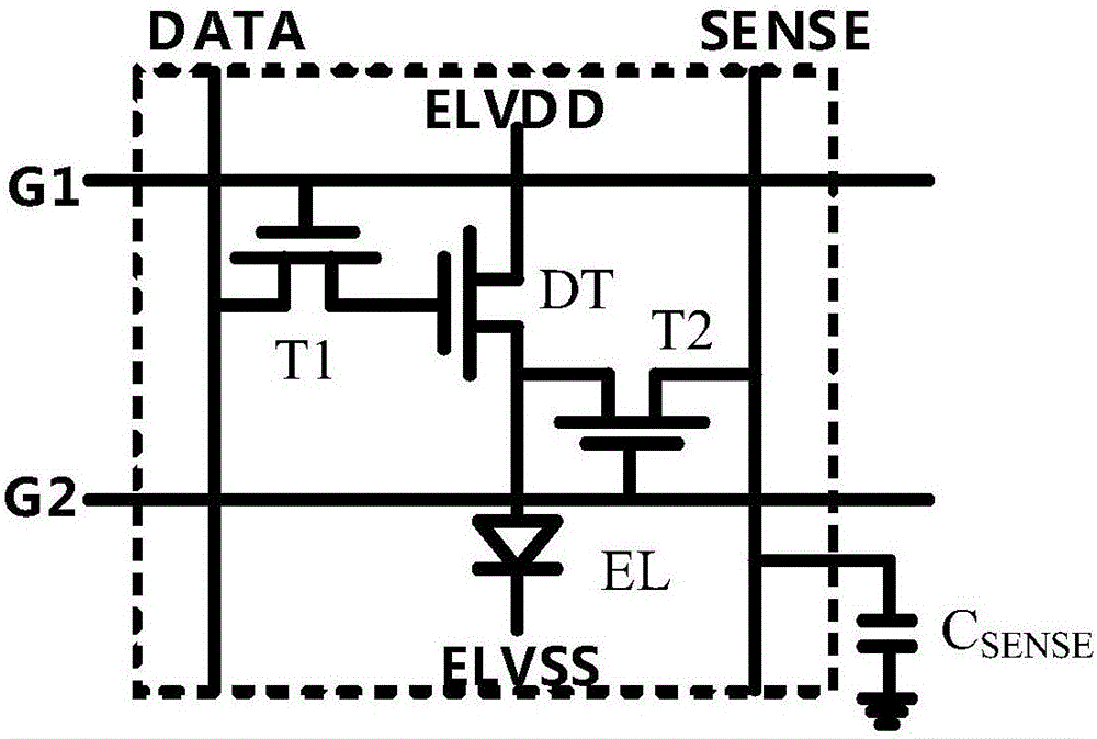
[0036] figure 1 A sub-pixel circuit is shown, and the sub-pixel circuit calibration device according to the embodiment of the present invention can be applied t...


PUM


Abstract

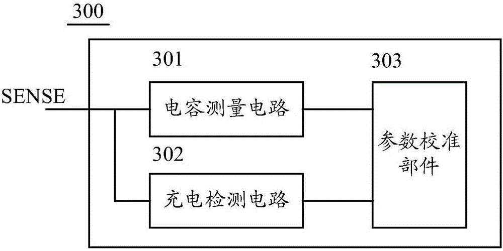
The invention provides a calibration device of a sub-pixel circuit, a source electrode driver and a data voltage compensation method. The sub-pixel circuit comprises a driving transistor, a data line and a sensing line. The calibration device comprises a capacitance measurement circuit, a charge detection circuit and a parameter calibration component, wherein the capacitance measurement circuit is used for outputting capacitance measurement voltage which is related with sensing line capacitance of the sensing line; the charge detection circuit is used for detecting capacitance charging voltage on the sensing line capacitance of the sensing line under the condition that reference data voltage is applied to the data line; and the parameter calibration component is used for calculating an electrical parameter of the driving transistor according to the capacitance measurement voltage, the reference data voltage and the capacitance charging voltage. Therefore, an electrical parameter drift condition of the driving transistor in the sub-pixel circuit can be determined, and thus data voltage applied to the sub-pixel circuit can be adjusted according to the electrical parameter drift condition, so that a circumstance of non-uniform display brightness caused by electrical parameter drift is compensated.

Description

technical field [0001] The present invention relates to the field of organic light-emitting display technology, and more particularly relates to a calibration device, a source driver and a data voltage compensation method for a sub-pixel circuit in an organic light-emitting display device. Background technique [0002] Organic light-emitting display diodes (OLEDs), as a current-mode light-emitting device, have been increasingly used in high-performance displays. In an active matrix organic light-emitting display (Active Matrix OLED), a row of pixels in the pixel array is sequentially selected by row-by-row scanning, and a data voltage is applied to the selected row of pixels, and the generated data is generated according to the applied data voltage. OLED current, so as to realize the light-emitting display of OLED. [0003] AMOLED mostly uses low-temperature polysilicon thin-film transistors (LTPS TFT) or oxide thin-film transistors (OxideTFT) to construct sub-pixel circuit...

Claims


Application Information

Patent Timeline
IPC IPC(8): G09G3/3225G09G3/3275H05B44/00
CPCG09G3/3225G09G3/3275G09G3/3233G09G2300/0842G09G2320/0295G09G2320/043G09G2320/0693G09G2310/0297G09G3/3291G09G2320/04
Inventor 吴仲远
Owner BOE TECH GRP CO LTD
Learn More