Liquid crystal backlight module group processing method with brightness induction adjustment

A processing method and technology of backlight module, applied in cooling/ventilation/heating transformation, instruments, electrical components, etc., can solve the problems of needing manual adjustment, no light emission, insufficiency, etc., to achieve artificial intelligence and improve service life Effect

Inactive Publication Date: 2016-11-09
HEFEI HUIKE JINYANG TECH
View PDF7 Cites 0 Cited by
  • Summary
  • Abstract
  • Description
  • Claims
  • Application Information

AI Technical Summary

Problems solved by technology

[0002] At present, the backlight is a kind of light source located behind the liquid crystal display. Its luminous effect will directly affect the visual effect of the liquid crystal display module. The liquid crystal itself does not emit light. It displays graphics or characters as the result of light modulation. With the development of the century, backlight has become an independent discipline of electronics, and has gradually become a research and development hotspot. The display of the traditional liquid crystal module is not equipped with a heat dissipation vent. During work, the light-emitting diodes in the backlight module will emit a lot of heat. It may cause the components inside the LCD module to age or even be damaged, resulting in a short service life of the entire LCD module and unable to meet people's needs. Moreover, the traditional backlight module does not have a brightness test module or a video type determination module inside. As a result, the module cannot automatically adjust the brightness according to the video type, and needs manual adjustment. It has not realized artificial intelligence, and cannot meet people's needs

Method used


Image

  • Liquid crystal backlight module group processing method with brightness induction adjustment
  • Liquid crystal backlight module group processing method with brightness induction adjustment

Examples


Embodiment Construction

[0010] The following will clearly and completely describe the technical solutions in the embodiments of the present invention with reference to the accompanying drawings in the embodiments of the present invention. Obviously, the described embodiments are only some, not all, embodiments of the present invention. Based on the embodiments of the present invention, all other embodiments obtained by persons of ordinary skill in the art without making creative efforts belong to the protection scope of the present invention.

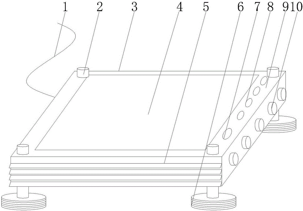
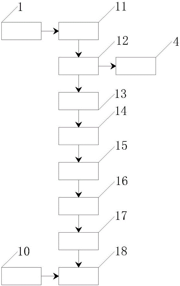
[0011] see figure 1 and figure 2 , an embodiment provided by the present invention: the product processed by the method of the present invention includes a display 3, a control panel 9, a signal input module 11, a video type determination module 14 and a drive current adjustment module 16, between the display 3 and the threaded fixture 6 Connected by the connecting shaft 2, and the threaded fixture 6 is installed below the display 3, the liquid crystal scree...


PUM


Abstract

A liquid crystal backlight module group processing method with brightness induction adjustment is disclosed. A display and thread fixing parts are connected through connection shafts. An output terminal of a signal input module is electrically connected to an input terminal of a video file playing module. An output terminal of the video file playing module is electrically connected to input terminals of a video brightness detection module and a liquid crystal screen. An output terminal of the video brightness detection module is electrically connected to an input terminal of a video type determining module. An output terminal of the video type determining module is electrically connected to an input terminal of an illuminator opening and closing module. An output terminal of the illuminator opening and closing module is electrically connected to an input terminal of a drive current adjusting module. An output terminal of the drive current adjusting module is electrically connected to an input terminal of the brightness automatic adjustment module. An output terminal of the brightness automatic adjustment module is electrically connected to an input terminal of a human-computer interaction module. The liquid crystal backlight module group processing method with brightness induction adjustment automatically adjusts the video brightness without artificial adjustment, realizes the artificial intelligence, and satisfies people' demands.

Description

technical field [0001] The invention relates to the technical field of liquid crystal backlight module equipment, in particular to a method for processing a liquid crystal backlight module with brightness induction adjustment. Background technique [0002] At present, the backlight is a kind of light source located behind the liquid crystal display. Its luminous effect will directly affect the visual effect of the liquid crystal display module. The liquid crystal itself does not emit light. It displays graphics or characters as the result of light modulation. With the development of the century, backlight has become an independent discipline of electronics, and has gradually become a research and development hotspot. The display of the traditional liquid crystal module is not equipped with a heat dissipation vent. During work, the light-emitting diodes in the backlight module will emit a lot of heat. It may cause the components inside the LCD module to age or even be damaged...

Claims


Application Information

Patent Timeline
Patent Type & Authority Applications(China)
IPC IPC(8): G09G3/34H05K7/20
CPCG09G3/3406H05K7/20954
Inventor 白航空
Owner HEFEI HUIKE JINYANG TECH
Why Eureka
Try Eureka