Proximity switch installation device

A technology of proximity switches and installation devices, applied in the direction of contact operating parts, etc., can solve the problems of unstable signals, harsh installation environment, poor detection of proximity switches, etc. The effect of equipment maintenance cycle

Active Publication Date: 2018-07-31
PANGANG GRP XICHANG STEEL & VANADIUM CO LTD
View PDF3 Cites 1 Cited by
  • Summary
  • Abstract
  • Description
  • Claims
  • Application Information

AI Technical Summary

Problems solved by technology

[0004] The detection distance of the common proximity switch is 15mm. In general applications, in order to ensure the stability of the signal, the installation detection distance is not greater than 10mm. It is very likely that the signal will be unstable and the proximity switch cannot be detected; if the proximity switch is adjusted too close to the detected equipment, when the precision of the mechanical equipment does not meet the requirements or the accuracy drops, or the mechanical equipment is not stable and shakes when it is running , it is easy to happen that the proximity switch is damaged by the baffle, which leads to equipment failure and shutdown. At the same time, the installation environment is bad and other factors cause maintenance difficulties, and problems such as poor detection of the proximity switch can cause major equipment failures.
[0005] The traditional fixed installation method is used to install the proximity switch on the coil unloading trolley and coil conveying trolley of the downcoiler of the hot rolling line. Due to the harsh working condition of the downcoiler and a lot of water, it often causes poor detection of the proximity switch or the wheels of the trolley and The wear of the roller table causes the running track of the trolley to deviate from the collision and damage the proximity switch. A series of other problems are caused by poor signal detection. In severe cases, major equipment accidents such as coil drop

Method used


Image

  • Proximity switch installation device
  • Proximity switch installation device
  • Proximity switch installation device

Examples


Embodiment Construction

[0019] The present invention will be further described below in conjunction with the accompanying drawings and embodiments.

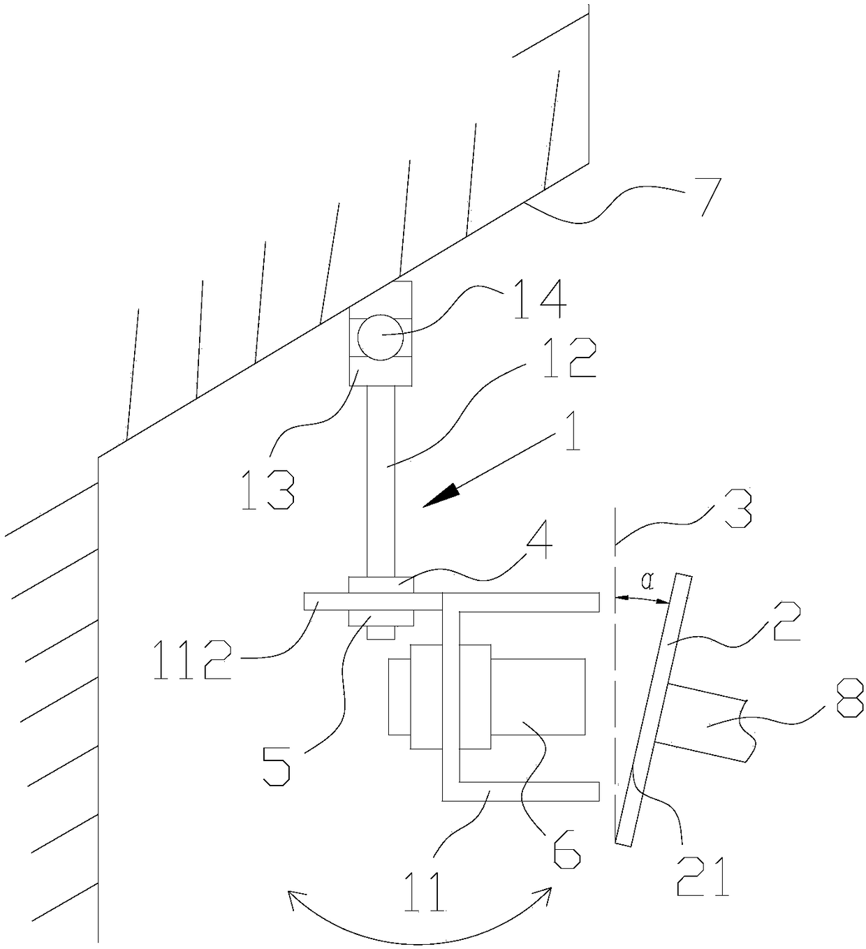
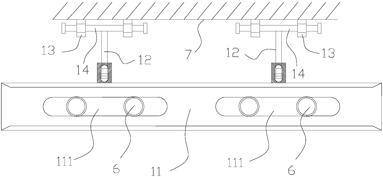
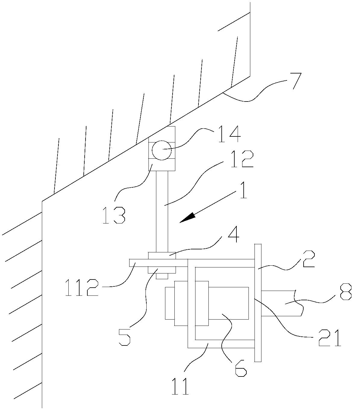
[0020] like figure 1 and figure 2 As shown, the installation device of the proximity switch of the present invention includes a mounting bracket 1 and a catch 2; the mounting bracket 1 includes a proximity switch mounting groove 11, a connecting rod 12 and a mounting seat 13, and the proximity switch mounting groove 11 is shaped groove; the first connecting end of the connecting rod 12 is connected with the proximity switch mounting groove 11, and the second connecting end of the connecting rod 12 is hinged with the mounting seat 13 through the hinge shaft 14, and the hinge shaft 14 is connected with the proximity switch The length direction of the switch installation groove 11 is parallel; the blocking piece 2 is installed on the detected device 8, and the angle α between the sensing surface 21 of the blocking piece 2 and the vertical surface 3 is 5-...


PUM


Abstract

The invention discloses a mounting apparatus of a proximity switch, comprising a mounting bracket and a baffle. The mounting bracket includes a proximity switch mounting groove, a connecting rod and a mounting seat. The proximity switch mounting groove is a U-shaped groove. A first connecting end of the connecting rod is connected with the proximity switch mounting groove. A second connecting end of the connecting rod is hinged with the mounting seat through an articulated shaft. The articulated shaft is in parallel to a length direction of the proximity switch mounting groove. The baffle is mounted on a device to be detected, and an included angle alpha of an induction surface and a vertical surface of the baffle is 5-15 degrees. An opening of the proximity switch mounting groove faces the induction surface of the baffle. The mounting apparatus of the proximity switch can prevent the proximity switch from being damaged, and can prolong the service life of the proximity switch. Meanwhile the device can swing in a large range and won't cause adverse detection of the proximity switch, and affects the detection stability and the device safety. The device fault hidden trouble caused by false detection is eliminated. It is convenient to adjust the mounting position and the mounting height of the proximity switch.

Description

technical field [0001] The invention relates to the field of automatic detection, in particular to an installation device of a proximity switch. Background technique [0002] Proximity switch is a commonly used detection method in automation systems. It is low in price, simple in application, and strong in adaptability. It can be used in harsh environments to ensure good detection. Proximity switch is a position switch that can issue operating instructions without mechanical contact with moving equipment. When the device moves to the sensing distance (also called detection distance) of the proximity switch, the proximity switch can send an action signal. When using a proximity switch to detect moving equipment in practical applications, the proximity switch is generally fixed in the proximity switch installation device, and the baffle is fixed on the device under test. Since the shutter has a relatively flat sensing surface, and the material is the same as that detectable b...

Claims


Application Information

Patent Timeline
Patent Type & Authority Patents(China)
IPC IPC(8): H01H3/16
CPCH01H3/16
Inventor 谢磊陈涛李柏儒
Owner PANGANG GRP XICHANG STEEL & VANADIUM CO LTD
Why Eureka
Try Eureka