Electronic switch power supply with front-and-back isolated arrangement

An electronic switch and power supply technology, applied in the direction of electrical components, output power conversion devices, etc., can solve problems such as electric shock accidents, poor switch sensitivity, etc., and achieve the effects of low cost, reduced ripple output, and simple circuit structure

Pending Publication Date: 2016-11-09
成都立威讯科技有限公司
View PDF0 Cites 0 Cited by
  • Summary
  • Abstract
  • Description
  • Claims
  • Application Information

AI Technical Summary

Problems solved by technology

[0004] In the prior art, when designing an electronic switch circuit, the ground terminals of the input circuit and the output circuit are often shared, resulting in mutual influence between the front and rear stages, poor switch sensitivity, and even electric shock accidents in severe cases.

Method used


Image

  • Electronic switch power supply with front-and-back isolated arrangement

Examples


Embodiment 1

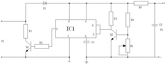
[0022] An electronic switching power supply adopting front and rear ground isolation settings, which isolates the ground of the input terminal from the ground of the filter output terminal, avoiding the occurrence of high voltage ripple coefficient when the front and rear are common ground, and can effectively improve the stability of the DC output, making the whole The DC power supply of the circuit is more stable, and the ripple output is reduced to prevent the power supply circuit of the subsequent stage from being unable to work normally due to the influence of the ripple, and further avoid reducing the service life of the circuit of the subsequent stage, such as figure 1 As shown, the following structure is specially arranged: an input circuit, a trigger control circuit, an inverter circuit and an output filter circuit are provided, the input circuit is connected to the trigger control circuit, the trigger control circuit is connected to the inverter circuit, and the invert...

Embodiment 2

[0025] This embodiment is further optimized on the basis of the above-mentioned embodiments, further to better realize the present invention, such as figure 1 As shown, the following arrangement structure is particularly adopted: the input circuit is provided with an input terminal Ui, an electronic switch tube Q1, a collector bias resistor R1, a base bias resistor R2 and a diode D1, and the collector bias resistor R1 The first end of the input terminal Ui is respectively connected to the anode of the diode D1, the second end of the collector bias resistor R1 is connected to the collector of the electronic switch tube Q1, and the cathode of the diode D1 is connected to the trigger control In the circuit, the base of the electronic switch tube Q1 is connected to the trigger control circuit through the base configuration resistor R2, and the emitter of the electronic switch tube Q1 is connected to the ground terminal of the input circuit.

[0026] The base bias resistor R2 provi...

Embodiment 3

[0028] This embodiment is further optimized on the basis of any of the above embodiments, further to better realize the present invention, such as figure 1 As shown, the following arrangement structure is particularly adopted: a transistor Q2, a collector bias resistor R3, a pull-up resistor R4, and a pull-down resistor W1 are arranged in the inverter circuit, and the collector of the transistor Q2 is respectively connected to the trigger control circuit and the The second end of the collector bias resistor R3 is connected, the first end of the collector bias resistor R3 is respectively connected to the trigger control circuit, the first end of the pull-up resistor R4 and the output filter circuit, and the first end of the pull-up resistor R4 Both terminals and the first terminal of the pull-down resistor W1 are connected to the base of the transistor Q2, and the emitter of the transistor Q2 and the second terminal of the pull-down resistor W1 are both connected to the ground t...


PUM


Abstract

The invention discloses an electronic switching power supply adopting front and rear isolation settings, which is provided with an input circuit, a trigger control circuit, an inverter circuit and an output filter circuit, the input circuit is connected to the trigger control circuit, and the trigger control circuit is connected to the inverter circuit , the inverter circuit is connected to the output filter circuit, the ground terminal of the input circuit is isolated from the ground terminal of the output filter circuit, and the ground of the input terminal is isolated from the ground of the filter output terminal, so as to avoid the high voltage ripple coefficient when the front and rear share the same ground. When the situation occurs, it can effectively improve the stability of the DC output, make the DC power supply of the entire circuit more stable, and reduce the ripple output, avoiding the power supply circuit of the subsequent stage from being unable to work normally due to the influence of the ripple, and further avoiding the reduction of the circuit of the subsequent stage. service life.

Description

technical field [0001] The invention relates to the technical field of electronic circuits, in particular, it is an electronic switching power supply with front and back isolation settings. Background technique [0002] An electronic switch refers to an operating unit that uses electronic circuits and power electronic devices to realize circuit switching, including at least one controllable electronic drive device, such as thyristors, transistors, field effect transistors, thyristors, relays, etc. However, in actual use, electronic switches mainly refer to wall switches such as touch switches, induction switches, voice-activated switches, and wireless switches. [0003] The 555 timer is a medium-scale integrated device that combines analog and digital functions. Generally, the bipolar (TTL) process is called 555, and the complementary metal oxide (CMOS) process is called 7555. In addition to the single timer, there are corresponding dual timers 556 / 7556. 555 timer The powe...

Claims


Application Information

Patent Timeline
Patent Type & Authority Applications(China)
IPC IPC(8): H02M1/14H02M1/08
CPCH02M1/14H02M1/08
Inventor 杨素贤
Owner 成都立威讯科技有限公司
Why Eureka
Try Eureka