digging tool

A technology of tools and drill bits, which is applied in the field of excavation tools, can solve problems such as difficult to suppress wear or damage of gauge blades, and achieve the effects of prolonging life, effectively drilling, and suppressing wear

Active Publication Date: 2019-03-26
菱技精密工具株式会社
View PDF9 Cites 0 Cited by
  • Summary
  • Abstract
  • Description
  • Claims
  • Application Information

AI Technical Summary

Problems solved by technology

However, for example, in the excavating tool described in the above-mentioned Patent Document 1, the front end surface of the pilot drill protrudes toward the front end side more than the annular drill, and only the pilot drill drills first, so it is difficult to suppress the wear or tear of the gauge blade. damage

Method used


Image

  • digging tool
  • digging tool
  • digging tool

Examples


Embodiment Construction

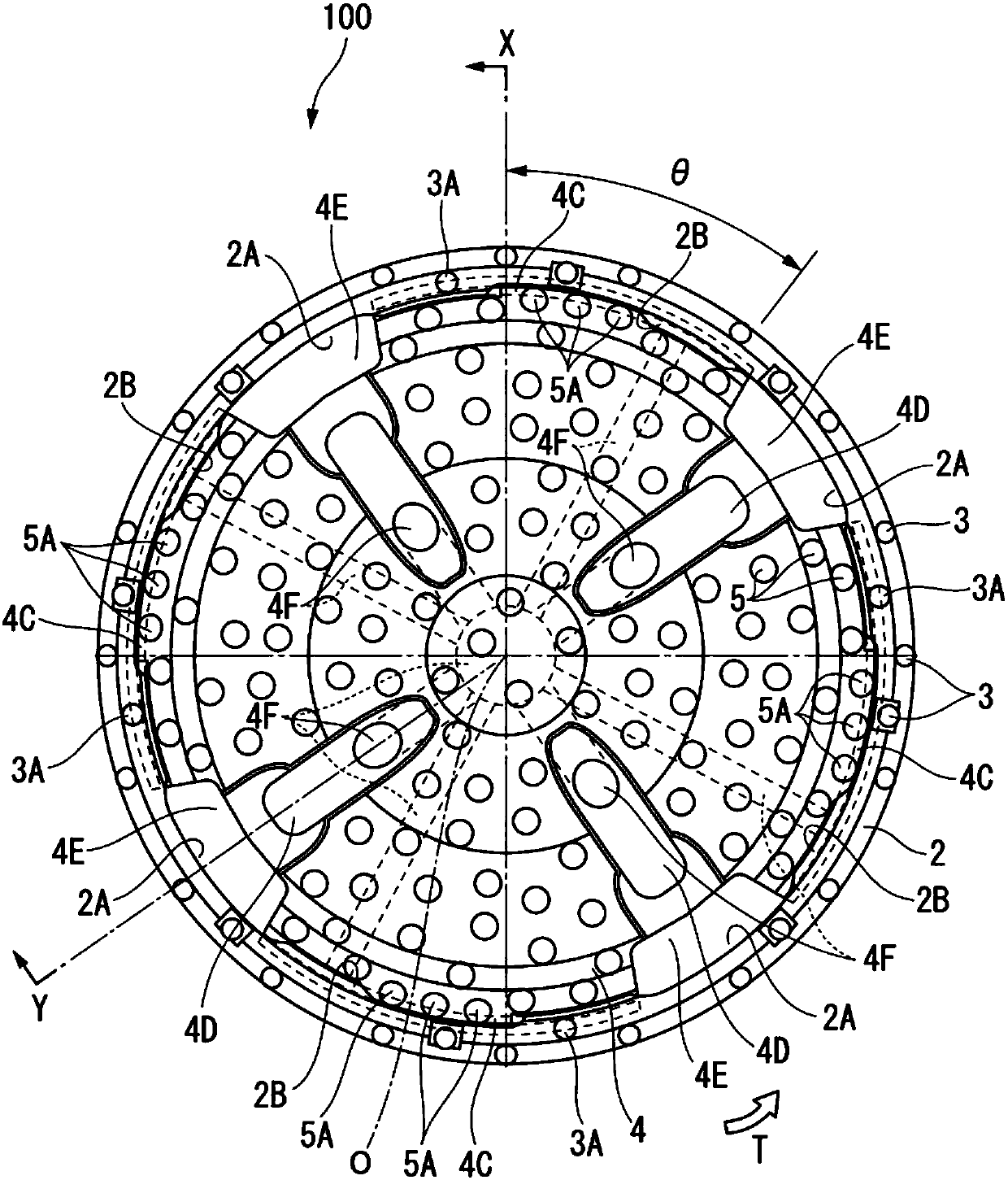
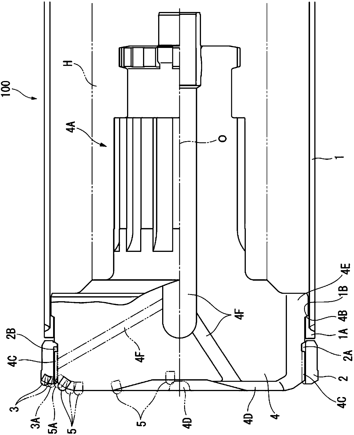
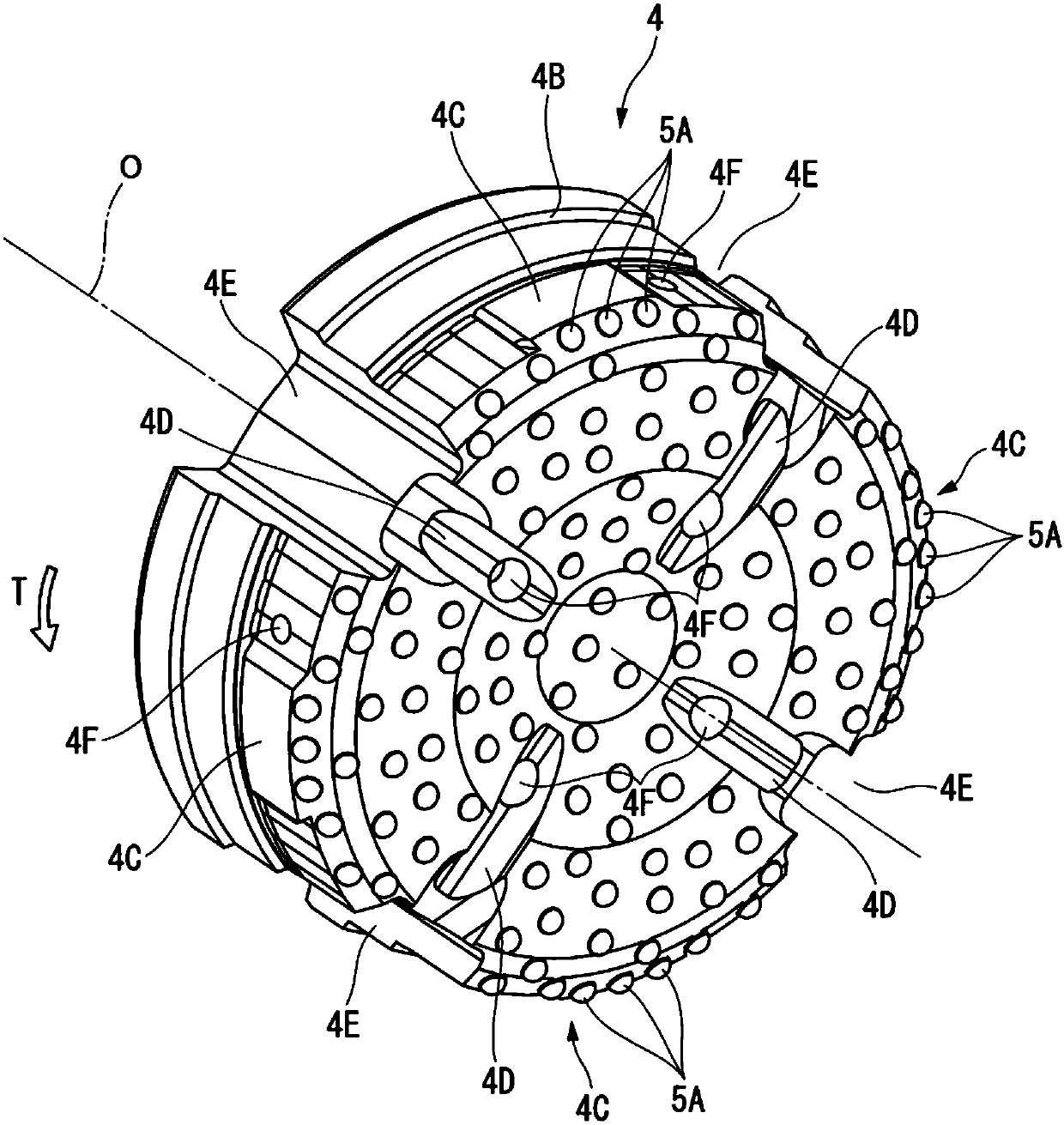
[0023] Figure 1 to Figure 4 It is a figure which shows the digging tool 100 which concerns on 1st Embodiment of this invention. Such as figure 2 As shown, in this embodiment, the bushing 1 is formed of steel or the like into a cylindrical shape centered on the central axis O, and at its tip ( figure 2 The left part in the center) is integrally mounted with a sleeve top 1A having an outer diameter equal to that of the sleeve 1 and a slightly smaller inner diameter by welding or the like. By attaching such a sleeve top portion 1A, a stepped portion 1B is formed on the inner periphery of the tip portion of the sleeve 1 so that the inner diameter becomes smaller by one step toward the tip side.

[0024] An annular ring drill 2 is disposed coaxially with the casing 1 and rotatably around the center axis O at the tip of the casing 1 . However, in this embodiment, if figure 2 As shown, the annular drill bit 2 is arranged at a distance from the casing top 1A in the direction o...


PUM


Abstract

According to one aspect of the excavation tool of the present invention, it includes: a cylindrical casing (1); A shaft is arranged so as to be rotatable around the central axis (O) of the casing (1); and a pilot bit (4) is inserted into the casing (1) from the rear end side and the tip of the pilot bit (4) The annular drill bit (2) is engaged with the pilot drill bit (4) in the rotation direction during excavation, so that the annular drill bit (2) can be connected to the pilot drill bit (O) around the central axis (O). 4) It rotates integrally and is locked on the distal end side in the direction of the central axis (O), excavating blades (5, 3) are protruded from the distal ends of the pilot bit (4) and the annular bit (2), and the pilot bit (4) ) of the outermost digging blade (5A) and the innermost digging blade (3A) of the annular drill (2) overlap on the rotation locus around the central axis (O) during excavation.

Description

technical field [0001] The present invention relates to an excavating tool for drilling through a ring drill arranged at the top of a casing and a pilot drill inserted into the casing and arranged at the inner periphery of the ring drill. [0002] This application claims priority based on Patent Application No. 2014-071558 for which it applied in Japan on March 31, 2014, and uses the content here. Background technique [0003] As such an excavating tool, there is known an excavating tool in which an annular ring drill bit is provided at the top end of a cylindrical casing so as to be rotatable around the axis of the casing, and is inserted into the casing. A pilot bit (inner bit) is attached to the tip of the transmission part inside the tube. In addition, for example, Patent Document 1 proposes an excavating tool in which first and second abutting portions that can be respectively abutted against a bushing and a ring drill are formed on the outer periphery of a pilot drill...

Claims


Application Information

Patent Timeline
Patent Type & Authority Patents(China)
IPC IPC(8): E21B10/36E21B10/26
CPCE21B7/208E21B7/20E21B10/64E21B10/26E21B10/265E21B10/46E21B10/60
Inventor 中村和由太田博士
Owner 菱技精密工具株式会社
Why Eureka
Try Eureka