
Heat source side unit and refrigeration cycle device

一种热源侧、侧单元的技术,应用在制冷机、制冷组件、制冷和液化等方向,能够解决采暖能力下降、耗费能量、时间等问题

Active Publication Date: 2016-11-09
MITSUBISHI ELECTRIC CORP
View PDF12 Cites 22 Cited by
  • Summary
  • Abstract
  • Description
  • Claims
  • Application Information

AI Technical Summary

Problems solved by technology

At this time, for example, when the defrosting is stopped according to the time, it is not judged whether the frost is completely melted (whether the defrosting is completed), and there is a problem that energy and time are wasted in vain due to the defrosting, or there is a problem due to the influence of the residual frost. The heating capacity of the heating operation after recovery is greatly reduced, etc.

Method used


Image

  • Heat source side unit and refrigeration cycle device
  • Heat source side unit and refrigeration cycle device
  • Heat source side unit and refrigeration cycle device

Examples


Embodiment approach 1

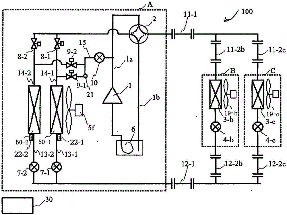
[0046] figure 1 It is a figure which shows the structure of the air-conditioning apparatus 100 which has a heat source side unit concerning Embodiment 1 of this invention. The air-conditioning apparatus 100 of the present embodiment includes: an outdoor unit A configured as a heat source side unit; and a plurality of indoor units (use side units) B and C connected in parallel. The outdoor unit A is connected to the indoor units B and C by the first extension pipes 11-1, 11-2b, 11-2c, and the second extension pipes 12-1, 12-2b, 12-2c to form a refrigerant circuit . The air conditioning device 100 also has a control device 30 . The control device 30 controls the cooling operation or heating operation (normal heating operation or heating defrosting operation) of the indoor units B and C. Here, the control device 30 of the present embodiment is constituted by, for example, a microcomputer or the like having a control arithmetic processing mechanism such as a central processing...

Embodiment approach 2

[0145] Figure 21 It is a figure which shows the structure of the air-conditioning apparatus 100 which concerns on Embodiment 2 of this invention. exist Figure 21 , for tags with figure 1 Devices and the like with the same reference numerals perform the same operations as those described in the first embodiment. Hereinafter, the air-conditioning apparatus 100 of this embodiment is demonstrated centering on the part which differs from the air-conditioning apparatus 100 of Embodiment 1. FIG.

[0146] In the air-conditioning apparatus 100 according to Embodiment 2, the compressor 1 has an injection port capable of introducing (injecting) the refrigerant from the outside of the compressor 1 in the compression chamber inside the compressor 1 that compresses the refrigerant.

[0147] In addition, the outdoor unit A of the air-conditioning apparatus 100 of the present embodiment has the second defrosting pipe 16 for passing the cooling air passing through the parallel heat excha...

Embodiment approach 3

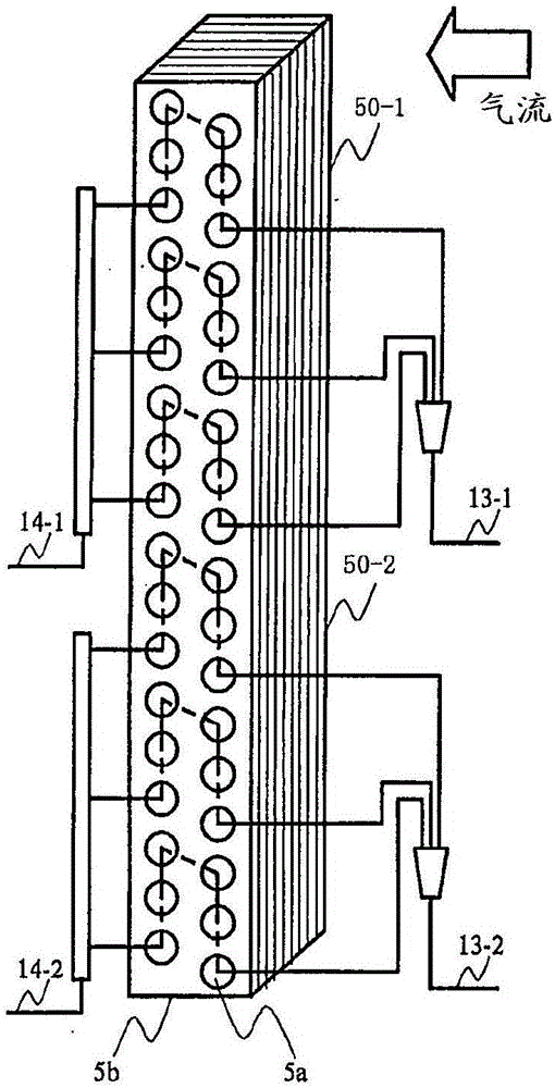
[0156] In Embodiment 1 and Embodiment 2 described above, an example in which the outdoor heat exchanger 5 is divided into a plurality of parallel heat exchangers 50-1 and 50-2 has been described, but the present invention is not limited thereto. For example, a structure including a plurality of independent outdoor heat exchangers 5 connected in parallel may be used. It is possible to perform a heating defrosting operation in which a part of the outdoor heat exchangers 5 are targeted for defrosting and the other outdoor heat exchangers 5 are used to continue the heating operation.


PUM


Abstract

An outdoor unit (A) that constitutes a refrigeration circuit by being connected by piping to indoor units (B, C) comprises: a compressor (1) that compresses and discharges a refrigerant; a plurality of parallel heat exchangers (50) that perform heat exchange between air and the refrigerant; a first defrost pipe (15) that forms a channel to perform defrosting by diverting a portion of the refrigerant discharged by the compressor (1) making the same flow to the parallel heat exchanger (50) to be defrosted; a first throttling device (10) that depressurizes the refrigerant that passes through the first defrost pipe (15); a second throttling device (7) that regulates the pressure of the refrigerant that passes through the parallel heat exchanger (50) to be defrosted; and a controlling device (30) that controls the second throttling device (7) so that the pressure of the refrigerant passing through the parallel heat exchanger (50) to be defrosted is within a predetermined range and that determines when defrosting is complete on the basis of the degree of supercooling of the refrigerant.

Description

technical field [0001] The present invention relates to a heat source side unit and the like in a refrigeration cycle device such as an air conditioner, for example. Background technique [0002] In recent years, from the viewpoint of global environmental protection, heat pump air conditioners using air as a heat source have been introduced in cold regions instead of boiler-type heating appliances burning fossil fuels for heating. In a heat pump type air conditioner, in addition to inputting electric power to a compressor, it is possible to efficiently perform heating in accordance with the heat supplied from the air. [0003] However, on the other hand, in the heat pump type air conditioner, the lower the temperature (outside air temperature) of the air (outside air) such as outdoors, the easier it is for the outdoor air to exchange heat with the refrigerant as an evaporator. Frost has formed on the heat exchanger. Therefore, it is necessary to perform defrosting (removal...

Claims


Application Information

Patent Timeline
Patent Type & Authority Applications(China)
IPC IPC(8): F25B47/02F25B1/00F25B5/00
CPCF25B13/00F25B47/022F25B2313/0233F25B2313/0251F25B2313/0253F25B2313/0315F25B2600/2513F25B47/02F28D1/0443F25B41/385
Inventor 竹中直史若本慎一渡边和也山下浩司鸠村杰
Owner MITSUBISHI ELECTRIC CORP
Learn More