fuel cell system

A technology of fuel cell system and fuel cell stack, which is applied in the direction of fuel cell, fuel cell additive, fuel cell heat exchange, etc., to achieve the effect of improving efficiency, low cost, and efficient fuel conversion

Active Publication Date: 2020-01-03
SIQENS
View PDF20 Cites 0 Cited by
  • Summary
  • Abstract
  • Description
  • Claims
  • Application Information

AI Technical Summary

Problems solved by technology

Therefore, additional fuel is required to heat the reformer

Method used


Image

  • fuel cell system
  • fuel cell system
  • fuel cell system

Examples


Embodiment Construction

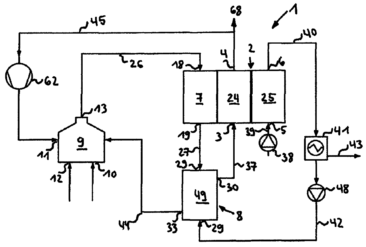
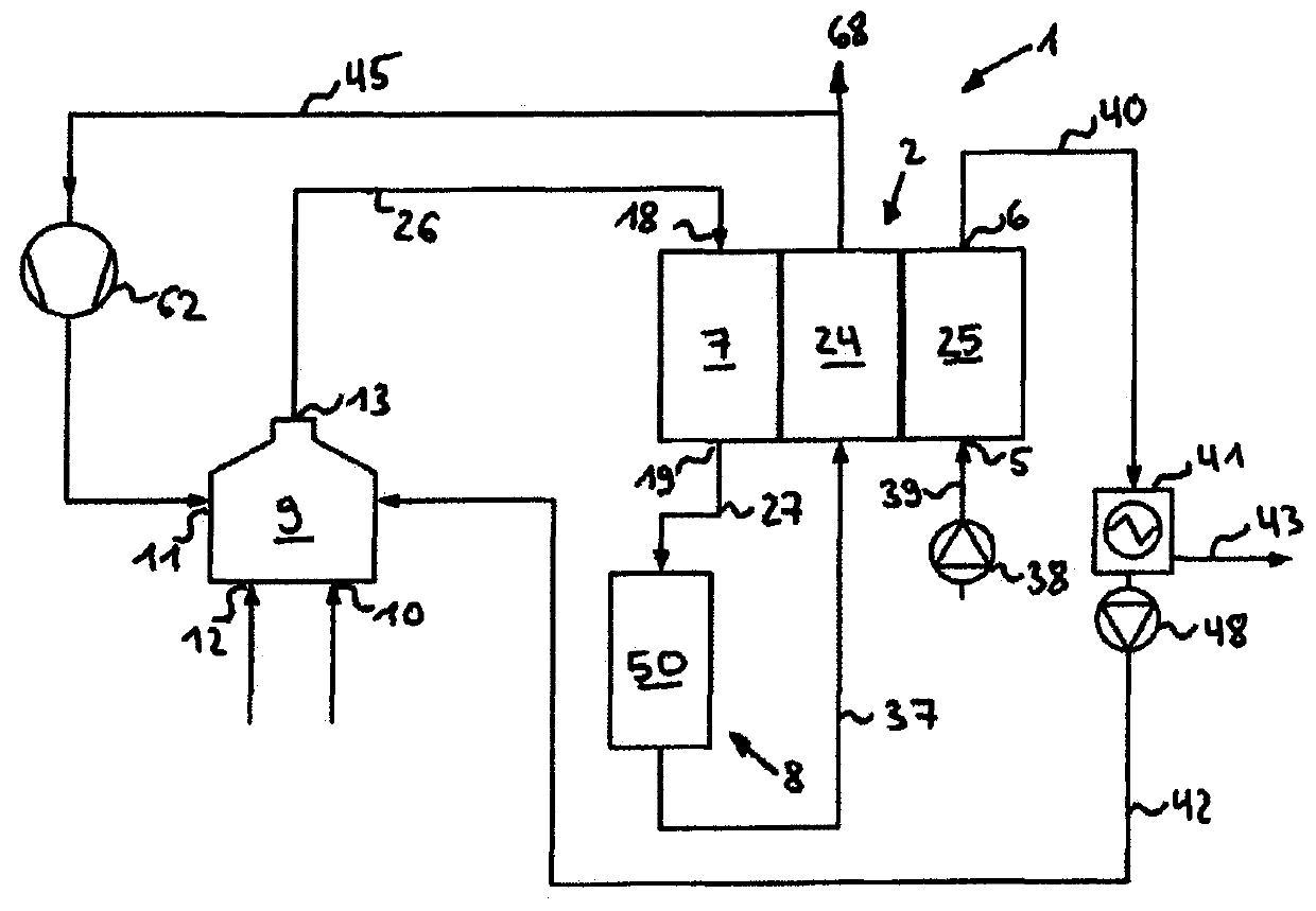
[0101] The fuel cell system 1 comprises, according to a first embodiment, a fuel cell or a fuel cell stack 2 having an anode 24 with an anode inlet 3 and an anode outlet 4 and a cathode 25 with a cathode inlet 5 and a cathode outlet 6 ( figure 1 ).

[0102] Furthermore, there is a reformer unit 7 thermally coupled to the fuel cell stack 2 for providing reformate or anode fluid, said reformer unit being connected upstream of the anode inlet 3 and present between the reformer unit 7 and the anode A treatment device (Aufbereitungseinrichtung) 8 is provided between the inlets 3 for removing untreated fuel and pollutants from the reformate.

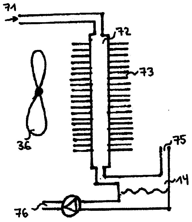
[0103] Furthermore, the fuel cell system 1 has a humidification unit 9 . The humidification unit 9 is constructed according to the humidification unit described in WO 2010 / 066900 and comprises: a humidification chamber configured to contain a fuel-containing liquid; an inlet 10 into the humidification chamber for delivering the fuel-containi...


PUM


Abstract

The present invention relates to a fuel cell system for internal, thermally coupled reforming with reformate preparation. This system includes a fuel cell stack have an anode inlet, an anode outlet, a cathode inlet and a cathode outlet. In addition, a reformer device, which is thermally coupled to the fuel cell stack, is provided for preparing an anode fluid that comprises reformed fuel, said reformer device being connected upstream of the anode inlet. A preparation device for removing non-reformed fuel and / or harmful substances from the anode fluid is arranged between the reformer device and the anode inlet.

Description

technical field [0001] The invention relates to a fuel cell system. Background technique [0002] DE 102 30 283 A1 discloses a method for cleaning the gas supplied to a fuel cell for the drive which is not conducive to the operation of the fuel cell. In this case, a filter system is arranged in the respective gas delivery channel, which filter system is designed to separate particles and harmful gases. Next, the gas is delivered to the fuel cell. The filter system is designed to separate particles as constituents in the form of gases or vapors, which have a detrimental effect on the operation of the fuel cell. Cleaning of the corresponding reaction gases by means of the filter system prevents deposits of dirt in the conveying channels, the conveying mechanism and the fuel cell itself, which impede the functioning of the fuel cell or cause harmful gases to react undesirably in the fuel cell. [0003] A method for operating a hydrocarbon reformer in a fuel cell system is kn...

Claims


Application Information

Patent Timeline
Patent Type & Authority Patents(China)
IPC IPC(8): H01M8/0612H01M8/0662H01M8/04007H01M8/04119H01M8/0668
CPCH01M8/04067H01M8/04126H01M8/04164H01M8/04171H01M8/0612H01M8/0618H01M8/0625H01M8/0662H01M8/0668H01M2008/1095Y02E60/50
Inventor 福尔克尔·哈尔布施
Owner SIQENS
Why Eureka
Try Eureka