A vibratory compacting ridge building machine

A technology of vibratory compaction and ridge building machine, which is applied in the fields of farming equipment, agricultural machinery and equipment, and application, etc., can solve the problem that the side warping piece of the ridge body increases the compaction effect, and cannot achieve the pressure bearing capacity of the ridge body and the top pressure of the ridge body. The problem of poor actual effect, etc., achieves the effect of novel product design, good compaction effect and low power consumption

Inactive Publication Date: 2018-04-27
NANJING AGRI MECHANIZATION INST MIN OF AGRI
View PDF5 Cites 0 Cited by
  • Summary
  • Abstract
  • Description
  • Claims
  • Application Information

AI Technical Summary

Problems solved by technology

The compaction and shaping of the ridge body in the current ridge-building machine are significantly affected by the amount of soil to build the ridge. When the soil amount is small, the compaction effect on the top of the ridge is poor, and the increase in the side of the ridge has a small compaction effect, which cannot meet the agronomic requirements. body pressure capacity

Method used


Image

  • A vibratory compacting ridge building machine
  • A vibratory compacting ridge building machine
  • A vibratory compacting ridge building machine

Examples


Embodiment 1

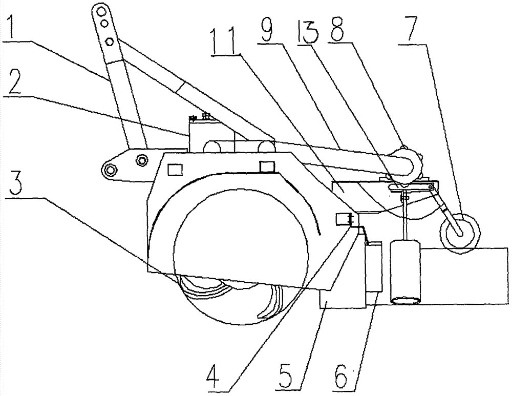
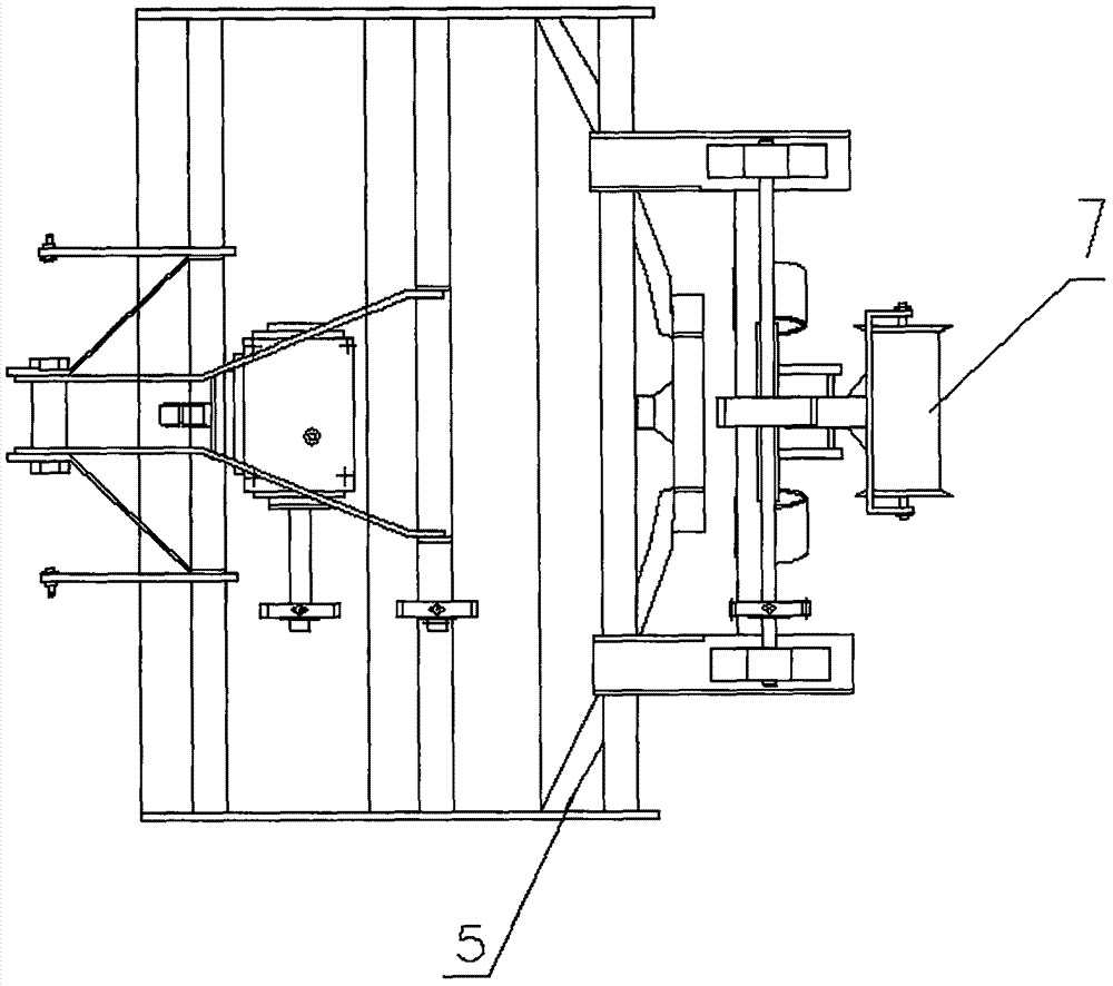
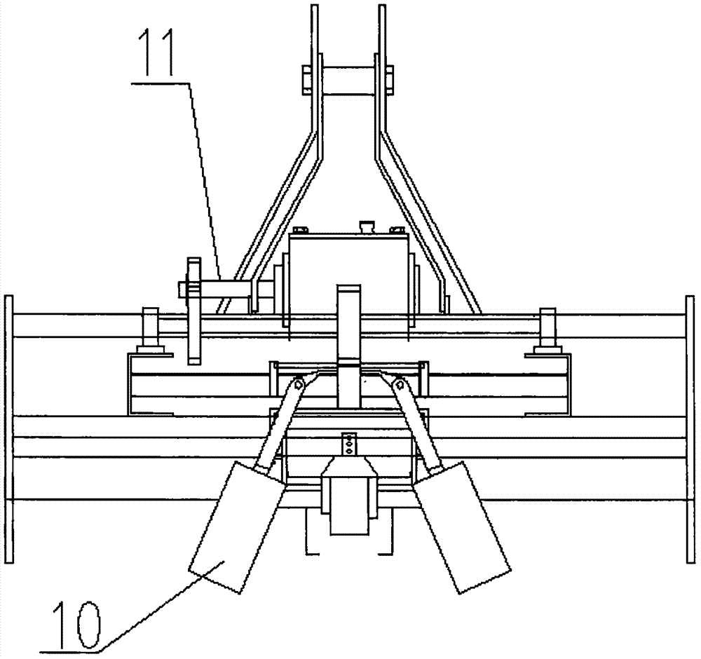
[0013] Such as figure 1 , figure 2 , image 3 Shown:

[0014] A vibration compacting ridge building machine, comprising a suspension frame 1, a frame, a gear box assembly 2, a rotary tiller assembly 3 and a chain drive assembly 9, the gear box assembly 2 is installed on the frame, and the gear box assembly Cheng 2 is connected with the rotary tiller assembly 3 through chain transmission, the rotary tiller assembly 3 includes the rotary tiller shaft and the rotary tiller, the bottom of the frame is also equipped with the top pressure plate 4, the rear of the rotary tiller assembly 3 The moldboard 5 is installed at the top, the moldboard 5 is connected with the side forming plate 6, and a vibration compacting device is installed at the tail of the frame. The vibration compacting device includes a side compacting roller 10, a cam 8, a top compacting roller 7 and the connecting bracket 12, the connecting bracket 12 is symmetrically installed on the tail of the frame, the left ...

Embodiment 2

[0016] Such as figure 1 , figure 2 , image 3 Shown:

[0017] A vibration compacting ridge building machine, comprising a suspension frame 1, a frame, a gear box assembly 2, a rotary tiller assembly 3 and a chain drive assembly 9, the gear box assembly 2 is installed on the frame, and the gear box assembly Cheng 2 is connected with the rotary tiller assembly 3 through chain transmission, the rotary tiller assembly 3 includes the rotary tiller shaft and the rotary tiller, the bottom of the frame is also equipped with the top pressure plate 4, the rear of the rotary tiller assembly 3 The moldboard 5 is installed at the top, the moldboard 5 is connected with the side forming plate 6, and a vibration compacting device is installed at the tail of the frame. The vibration compacting device includes a side compacting roller 10, a cam 8, a top compacting roller 7 and the connecting bracket 12, the connecting bracket 12 is symmetrically installed on the tail of the frame, the left ...


PUM


Abstract

The invention discloses a vibrating compaction ridger, and belongs to the technical field of agricultural machinery. The vibrating compaction ridger comprises a suspension bracket, a rack, a gearbox assembly, a rotary blade assembly and a chain transmission assembly, wherein the gearbox assembly is arranged on the rack and is connected with the rotary blade assembly through the chain transmission assembly, the rotary blade assembly comprises a rotary blade shaft and a rotary blade, the lower part of the rack is further provided with a top press plate which can be adjusted up and down, the back part of the rotary blade assembly is provided with a toe scraper, the toe scraper which is connected with a side forming plate, the side forming plate can be adjusted to the left and right, and the tail part of the rack is further provided with a vibrating compaction device. The vibrating compaction ridger is mainly applied to the aspect of agricultural ridging.

Description

technical field [0001] The invention belongs to the technical field of agricultural machinery, in particular to a vibration compacting ridge building machine. Background technique [0002] The so-called ridge-building machine usually refers to a machine tool used for fields such as building ridges and repairing old ridges in the field, so as to store water in the field and allow staff to walk on the ridges. Field ridge building is an important part of land preparation for mechanized rice production. According to the position of the ridge building parts, the machine can be divided into the middle ridge type and the side ridge type; according to the different soil extraction devices, it can be divided into the plow type, rotary tiller type, etc.; Complete, the compaction of the ridge soil is completed by passive or driven double horn-shaped rollers. In order to ensure the stability and pressure bearing capacity of the built ridge, the surface of the trumpet cone is designed ...

Claims


Application Information

Patent Timeline
Patent Type & Authority Patents(China)
IPC IPC(8): A01B33/02A01B33/12
CPCA01B33/022A01B33/12
Inventor 朱继平陈伟袁栋丁艳夏敏姚克恒陈小兵
Owner NANJING AGRI MECHANIZATION INST MIN OF AGRI
Why Eureka
Try Eureka