Crankshaft rotating machine
A rotary machine and crankshaft technology, applied in the field of crankshaft rotary machines, can solve the problems of difficult fine-tuning, poor positioning, tripping, etc., and achieve the effect of humanized equipment and high operation accuracy
- Summary
- Abstract
- Description
- Claims
- Application Information
AI Technical Summary
Problems solved by technology
Method used
Image

Examples
Embodiment Construction
[0014] Below, the substantive features and advantages of the present invention will be further described in conjunction with examples, but the present invention is not limited to the listed examples.
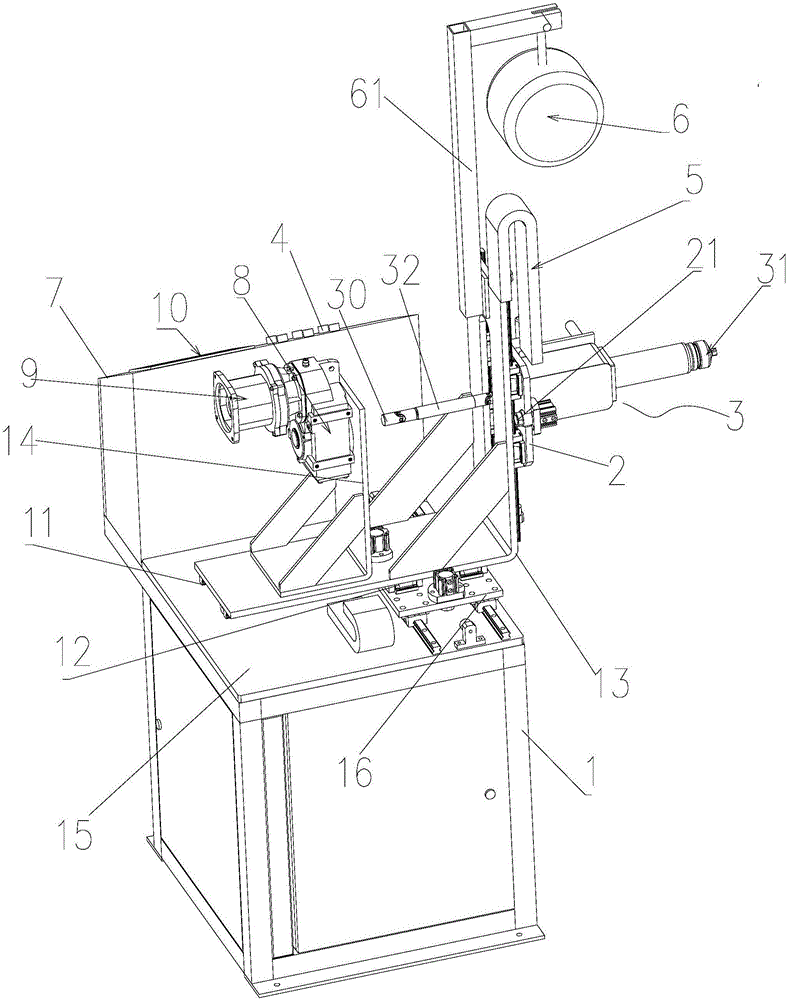
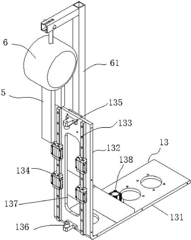
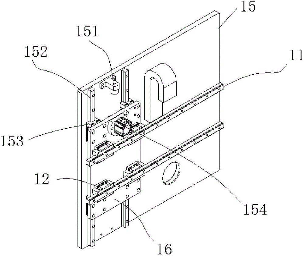
[0015] see Figure 1-5 As shown, a crankshaft rotating machine includes an underframe 1, an electrical cabinet (not shown) is arranged inside the underframe, a UVW moving part of a working head and an operation cabinet 7 are arranged above the underframe, and the The operation cabinet is provided with a display screen 10 and operation buttons 4, and the UVW moving part includes a V-direction mobile panel 16 that can move in the V direction and is connected to the installation panel 15 through the V-direction slide rail 152 and the matching slider 153. The upper end surface of the V-direction mobile panel is connected to the lower end surface of the horizontal part 131 of the U-shaped L-shaped U-direction mobile plate 13 connected by the U-direction slide rail 11 and the slider 1...
PUM
 Abstract
Description
Claims
Application Information