Feed and discharge processing method and feed and discharge processing device of flat-head machine and flat-head machine

A processing method and processing device technology, applied in metal processing, etc., to achieve the effects of improving processing efficiency, improving versatility, and avoiding material jamming

Active Publication Date: 2016-11-16
ZHUZHOU KAIFENG IND
View PDF9 Cites 15 Cited by
  • Summary
  • Abstract
  • Description
  • Claims
  • Application Information

AI Technical Summary

Problems solved by technology

[0008] However, after the above improvements, although the processing efficiency of the pipe fitting flat head machine has been improved to a certain extent, the applicant believes that there is still room for further improvement in the processing efficiency of the pipe fitting flat head machine

Method used


Image

  • Feed and discharge processing method and feed and discharge processing device of flat-head machine and flat-head machine
  • Feed and discharge processing method and feed and discharge processing device of flat-head machine and flat-head machine
  • Feed and discharge processing method and feed and discharge processing device of flat-head machine and flat-head machine

Examples


Embodiment 1

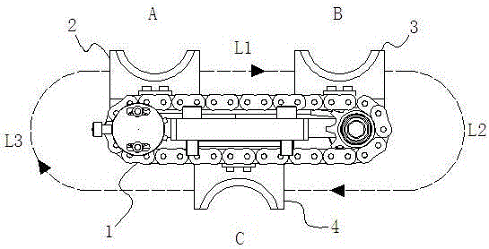
[0037] Embodiment 1: In this embodiment, the upper and lower material processing devices with three lower clamps are set to specify: as figure 1 and figure 2 Shown, a kind of loading and unloading processing method of flat head machine, described loading and unloading method is to arrange a belt transmission mechanism, three lower clamps are arranged on the transmission belt 1 of the belt transmission mechanism, and the transmission belt 1 top One end of the pipe fittings is set as the loading position A of the pipe fittings, the other end of the upper part of the transmission belt 1 is set as the processing position B of the pipe fittings, and the lower part of the transmission belt 1 is set as the unloading position C of the pipe fittings; Driven by the drive, each lower fixture circulates in turn from the loading position to the processing position to the unloading position and then to the loading position, so that the three steps of loading, processing and unloading of pi...

Embodiment 2

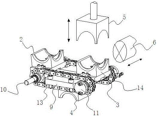
[0055] Embodiment 2: as Figure 9 As shown, compared with Embodiment 1, the difference is that an anti-jamming mechanism is provided on one side of the upper clamp 5, and the anti-jamming mechanism includes a connecting block 37, a compression spring 38 and a top block 39; the connecting block 37 is arranged on one side of the upper fixture 5, one end of the stage clip 38 is connected with the connection block 37, and the other end of the stage clip 38 is connected with the top block 39, when the upper fixture can cooperate with the lower fixture at the processing position, it will be positioned at the processing position. When the pipe fittings in the lower fixture at the position are clamped, the top block 39 is in contact with the pipe fittings, and the clip spring 38 is in a pressed state. During the flat end processing of pipe fittings, since the upper fixture needs to be pressed down to cooperate with the lower fixture to clamp the pipe fittings, after the upper fixture ...

Embodiment 3

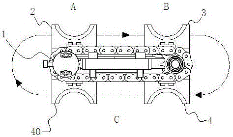
[0056] Embodiment 3: as Figure 10 As shown, compared with Embodiment 1, the difference is that there are four lower clamps arranged on the transmission belt, which are lower clamp one 2, lower clamp two 3, lower clamp three 4 and lower clamp four 40. Wherein, lower clamp one 2 is located at loading position A, lower clamp two 3 is located at processing position B, and lower clamp three 4 and lower clamp four 40 are both located at unloading position C.

[0057] To sum up, the present invention integrates the three steps of loading, processing and unloading of pipe fittings on the same transmission belt to complete simultaneously, that is, when the lower clamp located at the loading position performs loading of the pipe fittings, the clamp located at the processing position carries out For flat head processing, the pipe fittings at the unloading position are unloaded at the same time, which greatly shortens the processing time of pipe fittings and greatly improves the processi...


PUM


Abstract

The invention discloses a feed and discharge processing method and a feed and discharge processing device of a flat-head machine and the flat-head machine. According to the feed and discharge processing method, a belt transmission mechanism is arranged, three or more than three lower fixtures are arranged on a transmission belt of the belt transmission mechanism, a feed position of a pipe is set in one end of the upper part of the transmission belt, a processing position of the pipe is set on the other end of the upper part of the transmission belt, and a discharge position of the pipe is set in an area of the lower part of the transmission belt. During processing, each lower fixture is driven to pass through the feed position, the processing position and the discharge position and then return to the feed position by the transmission belt, so as to form a circulation, so that the feed, processing and discharge steps of the pipe are completed on the same transmission belt at the same time. According to the feed and discharge processing method, the feed and discharge processing device and the flat-head machine, the processing efficiency of the pipe flat-head machine is greatly improved.

Description

technical field [0001] The invention relates to a working method of a pipe fitting flattening machine, a working part of the pipe fitting flattening machine using the working method, and a pipe fitting flattening machine including the working parts, in particular to a processing method for loading and unloading of the flattening machine, as well as loading and unloading. Material processing device and flat head machine. Background technique [0002] Malleable steel pipe fittings such as straight pipes, tee pipes and elbows need to be flattened before leaving the factory to ensure quality. Generally, a flattening machine is used to flatten malleable steel pipe fittings. The processing efficiency of the flattening machine is an important factor affecting the benefit of malleable steel pipe fittings. The higher the processing efficiency, the higher the output of malleable steel pipe fittings and the greater the benefit. Many manufacturers pay great attention to improving the pr...

Claims


Application Information

Patent Timeline
Patent Type & Authority Applications(China)
IPC IPC(8): B23Q7/03B23Q7/14B23D79/00
Inventor 尹高平赵峰
Owner ZHUZHOU KAIFENG IND
Why Eureka
Try Eureka