
A kind of polysilicon reduction method

A polysilicon and reduction furnace technology, applied in chemical instruments and methods, silicon compounds, inorganic chemistry, etc., can solve the problems of reducing the reduction power consumption of the reduction furnace, destroying the polished surface, and short-circuiting the raw material gas, so as to achieve easier control of growth quality, The effect of uniform temperature distribution and reduction of reduction power consumption

Active Publication Date: 2018-04-06
NANJING DUBLE METAL EQUIP ENG
View PDF6 Cites 0 Cited by
  • Summary
  • Abstract
  • Description
  • Claims
  • Application Information

AI Technical Summary

Problems solved by technology

The gas inlet and outlet methods of the traditional reduction furnace are also easy to cause the raw material gas to short circuit, so that the raw material gas is directly discharged from the gas outlet without sufficient reaction, resulting in waste of raw material gas and affecting the deposition rate of polysilicon
Compared with the old and new reduction furnaces, the temperature distribution of the new reduction furnace has a more obvious temperature difference in the axial direction of the reduction furnace. This is because the flow field in the new polysilicon reduction furnace is a horizontal push flow, which can be changed by changing The operating conditions of the reduction furnace are used to control the temperature of each position in the reduction furnace. The controllable temperature distribution can control the production of silicon powder in the reduction furnace, and prevent the silicon powder from adhering to the inner wall of the reduction furnace and destroying the polishing of the inner wall of the reduction furnace. The polished surface of the inner wall of the reduction furnace can be preserved for a long time, which increases the reflection of the inner wall to the heat radiation of the high-temperature silicon rod, thereby reducing the reduction power consumption of the reduction furnace; while the flow field in the traditional reduction furnace is a full mixed flow, its temperature The distribution is more uniform. This flow method cannot effectively control the temperature in the reduction furnace, so it is easy to generate a local high temperature area in the reduction furnace. This local high temperature area will produce silicon powder, and the silicon powder is easy to adhere to the inner wall of the reduction furnace. surface, causing the generation of local high-temperature spots on the inner wall of the reduction furnace, and this local high-temperature point will cause more silicon powder to adhere, eventually destroying the polished surface of the inner wall of the reduction furnace, thereby increasing the reduction power consumption of the reduction furnace

Method used


Image

  • A kind of polysilicon reduction method
  • A kind of polysilicon reduction method

Examples


Embodiment Construction

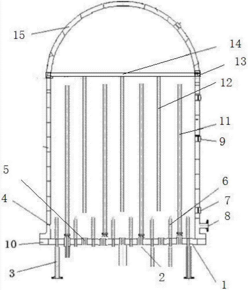
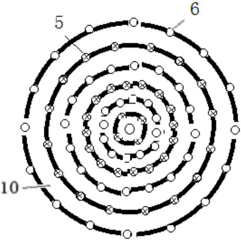
[0014] As shown in the figure, the furnace bottom 1, the electrode bracket 2, the furnace foot 3, the furnace wall 4, the gas outlet 5, the air inlet pipe 6, the observation mirror 7, 9, the furnace wall spare gas outlet 8, the air inlet pipe installation plate 10, Electrode 11, hoisting electrode 12, hoisting electrode installation position 13, hoisting electrode installation bracket 14, hemispherical top furnace cavity 15.

[0015] The invention includes: a chassis and a furnace body, the furnace body is the upper part of the chassis, and the furnace body is a reaction chamber with a cylindrical shape and a hemispherical top; 30-50 pairs of electrodes are evenly distributed on the top (depending on the size of the furnace body, including the hoisting electrodes). The half of the electrodes are evenly installed vertically on the chassis, and the other half of the electrodes are hoisting electrodes, which are interlaced with the vertically installed electrodes on the chassis. ...


PUM


Abstract

Provided is a polycrystalline silicon reduction method. A polycrystalline silicon reduction furnace is adopted in the method. The reduction furnace comprises a base plate and a furnace body. The furnace body is arranged on the base plate and is a cylindrical reaction cavity with a hemispherical dome. The base plate is in a disc shape, feed gas inlets and tail gas outlets are evenly distributed in the base plate, 30-50 pairs of electrodes are evenly distributed on the base plate, one half of the electrodes are evenly and vertically installed on the base plate, the other half of the electrodes are hoisting electrodes, the hoisting electrodes and the electrodes vertically installed on the base plate are distributed in a staggered mode, the distance of the bottom ends of the hoisting electrodes and the base plate is 3-10 cm, and the upper ends of the hoisting electrodes are flush with the junction of the cylinder and the hemispherical dome. The feed gas inlets and tail gas outlets are evenly distributed in the circumferences of different radii of the base plate, and when the corresponding feed gas inlets are formed in the circumference of one radius, the corresponding tail gas outlets are formed in the circumference of the adjacent radius. Temperature sensors are arranged on the upper end planes of the hoisting electrodes, and the flow of feed gas is controlled to make the temperature of the temperature sensors reach 910-935 DEG C.

Description

1. Technical field [0001] The invention relates to a polysilicon reduction furnace and a method for polysilicon reduction. 2. Background technology [0002] At present, the polysilicon production processes in the world include: improved Siemens method, silane method and fluidized bed method. Among them, the improved Siemens method is the main process of polysilicon production at present, and its polysilicon production accounts for 80% of the world's total polysilicon production. The most important equipment in this process is the polysilicon reduction furnace, and its reduction power consumption exceeds the total power consumption of the entire polysilicon production process. 60%. Therefore, it is of great academic and practical value to conduct in-depth research on the flow structure in the reduction furnace, and then develop a new type of reduction furnace with low energy consumption. [0003] In the structure of the traditional polysilicon reduction furnace, the inlet o...

Claims


Application Information

Patent Timeline
Patent Type & Authority Patents(China)
IPC IPC(8): C01B33/021
CPCC01B33/021
Inventor 黄雪李岩张建新张海峰
Owner NANJING DUBLE METAL EQUIP ENG
Learn More