A method for making and installing cast-in-place box girder formwork

An installation method and formwork technology, applied to bridges, bridge construction, erection/assembly of bridges, etc., can solve problems such as complex construction process, poor surface quality, and short service life, and achieve high construction quality, light weight, and long service life long effect

Active Publication Date: 2017-09-26
CHINA THIRD METALLURGICAL GRP
View PDF5 Cites 0 Cited by
  • Summary
  • Abstract
  • Description
  • Claims
  • Application Information

AI Technical Summary

Problems solved by technology

[0003] At present, the formwork used for cast-in-place box girders mostly uses steel formwork, which has the disadvantages of heavy weight, many joints, poor surface quality after pouring, difficult demoulding, low turnover times, and short service life
In addition, during the construction of the bridge, the drip groove and the chamfering of the bridge body need to be constructed with special formwork, the processing cost is high, and the construction process is complicated

Method used


Image

  • A method for making and installing cast-in-place box girder formwork
  • A method for making and installing cast-in-place box girder formwork
  • A method for making and installing cast-in-place box girder formwork

Examples


Embodiment Construction

[0033] The specific embodiment of the present invention will be further described below in conjunction with accompanying drawing:

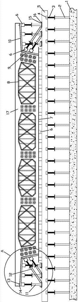
[0034] Such as figure 1 As shown, a method for making and installing a cast-in-place box girder formwork according to the present invention comprises the following steps:

[0035] 1) Manufacture of cast-in-place box girder formwork;

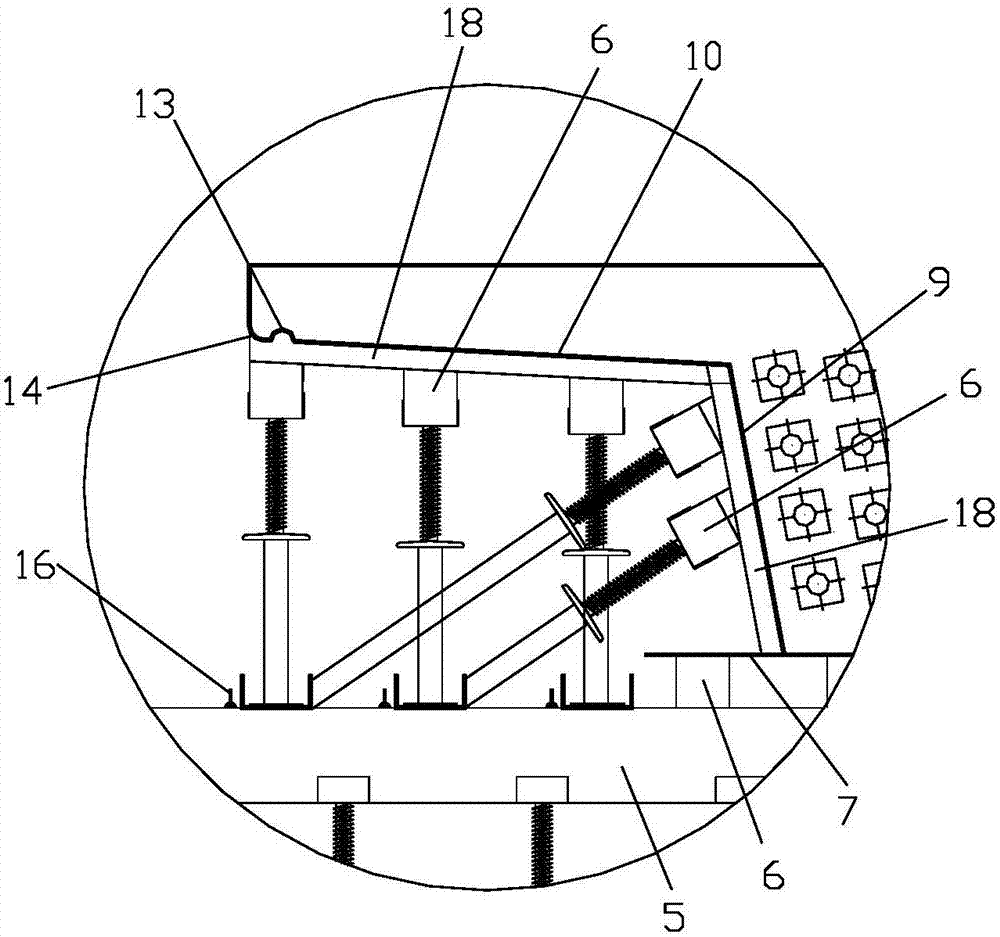
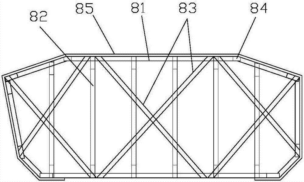
[0036] a. The cast-in-place box girder formwork includes the bottom formwork 7 placed at the bottom of the bridge body 17, the box chamber formwork 8 placed inside the bridge body 17, the side formwork 9 placed on both sides of the bridge body 17 and placed on both sides of the bridge body 17 The flange plate formwork 10 at the bottom of the extended end; the cast-in-place box girder formwork is all made of clear water formwork. In order to reduce the formwork joints, the largest specification clear water formwork of 2440m×1220mm is preferred when the size is suitable;

[0037] b. The bottom formwork 7 and the side...


PUM


Abstract

The invention relates to a cast-in-situ box girder formwork manufacturing and mounting method. The cast-in-situ box girder formwork manufacturing and mounting method comprises the steps of (1) manufacturing a cast-in-situ box girder formwork, specifically, the cast-in-situ box girder formwork is completely made of a fair-faced formwork, and a box formwork is composed of a plurality of sets of supporting frames evenly arranged in the longitudinal direction of the box formwork, and a peripheral formwork body arranged on the periphery of the supporting frames; and (2) mounting the cast-in-situ box girder formwork, specifically, a soffit formwork, the box formwork, a flange plate formwork and side formworks are mounted in sequence, and larmiers and a chamfer on the outer side of a bridge flange are formed at a time. According to the cast-in-situ box girder formwork manufacturing and mounting method, the cast-in-situ box girder formwork is completely made of the fair-faced formwork and has the advantages that the self weight is low, the breadth is large, the strength is high, demolding is easy, the surface is smooth and attractive after pouring, and the construction performance is good, and is more suitable for construction of large bridges; and the cast-in-situ box girder formwork manufacturing and mounting method is simple, construction is convenient, the larmiers and the chamfer on the outer side of the bridge flange can be formed at a time during pouring, and the construction quality is high.

Description

technical field [0001] The invention relates to the technical field of bridge construction, in particular to a method for manufacturing and installing a cast-in-place box girder formwork. Background technique [0002] In bridge construction, box girders of reinforced concrete structure are divided into prefabricated box girders and cast-in-place box girders. Among them, cast-in-place box girders are mostly used in the construction of large continuous bridges. The construction process is: support foundation construction-bracket installation-bottom formwork installation-bracket Preloading - preloading unloading - adjusting the elevation of the bottom formwork - installation of bottom plate and web reinforcement and prestress - installation of side formwork and inner formwork (box chamber formwork) - pouring bottom plate and web concrete - removal of inner formwork - roof reinforcement and prestress Installation - pouring roof concrete - curing - tensioning - channel grouting -...

Claims


Application Information

Patent Timeline
Patent Type & Authority Patents(China)
IPC IPC(8): E01D21/00
CPCE01D21/00
Inventor 宿巳光王虎成宋秀成
Owner CHINA THIRD METALLURGICAL GRP
Why Eureka
Try Eureka