Split Hopkinson pressure bar electromagnetic buffering and energy absorbing device

A Hopkinson pressure bar and energy-absorbing device technology, applied in the directions of magnetic springs, springs, springs/shock absorbers, etc., can solve the problems of poor operability and economy, inability to dissipate energy in time, and high impact strength. Intelligence and security, to achieve the effect of regulating the strength of the magnetic field and high reuse rate

Active Publication Date: 2016-11-16
HARBIN ENG UNIV
View PDF6 Cites 3 Cited by
  • Summary
  • Abstract
  • Description
  • Claims
  • Application Information

AI Technical Summary

Problems solved by technology

[0003] At present, the general idea for the design of Hopkinson rod absorbing rods is to use traditional materials such as foam and rubber, and the functional design of its buffer energy absorption is relatively simple, which cannot achieve a complete buffer energy absorption effect, and its operability and economy sex is also relatively poor
From the current research on absorbing rod energy-absorbing devices, it is found that the design idea of ​​most absorbing rod energy-absorbing devices is to use the principle of piston buffering and spring shock absorption to achieve the purpose of energy-absorbing buffering, although it can be seen from the results that Purpose, considering that the impact speed of the Hopkinson rod is relatively fast and the impact strength is high, it is easy to cause local deformation of the impact rod, the rod parts fall off, and even the damage of the absorbing rod device may be caused due to the inability to dissipate the energy in time

Method used


Image

  • Split Hopkinson pressure bar electromagnetic buffering and energy absorbing device
  • Split Hopkinson pressure bar electromagnetic buffering and energy absorbing device
  • Split Hopkinson pressure bar electromagnetic buffering and energy absorbing device

Examples


Embodiment Construction

[0013] The present invention will be further described in detail below in conjunction with the accompanying drawings and specific embodiments.

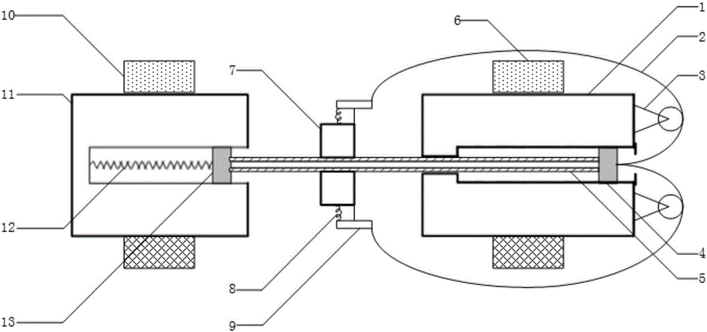
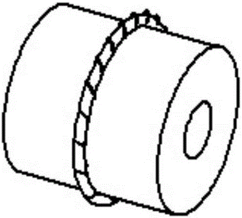
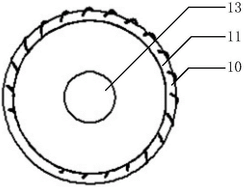
[0014] combine Figure 1 to Figure 4 , the present invention includes: No. 1 metal base 1, two ropes 2, two fixed pulleys 3, No. 1 iron block 4, metal connecting rod 5, and ring electromagnet 6 form the first layer of impact energy-absorbing system; ring brake 7. No. 2 spring 8 and two groups of levers 9 form the second layer of impact energy absorption system; No. 2 metal base 10, ring electromagnet 11, No. 1 spring 12, and No. 2 iron block 13 form the third layer of impact energy absorption system. The hoop brake 7 can be spliced ​​by upper and lower semicircular brakes.

[0015] In the first layer of impact energy-absorbing device and the third layer of impact energy-absorbing device, the external power supply is used to directly supply power to the ring electromagnet 6 and the ring electromagnet 10, and the magnetic field of the...


PUM


Abstract

The invention provides a split Hopkinson pressure bar electromagnetic buffering and energy absorbing device comprising a first-layer impact bearing energy absorbing system, a second-layer impact bearing energy absorbing system and a third-layer impact bearing energy absorbing system, wherein the first-layer impact bearing energy absorbing system is composed of a first metal base, two ropes, two fixed pulleys, a first iron block, a metal connecting rod and an annular electromagnet; the second-layer impact bearing energy absorbing system is composed of an annular brake, a second spring and two groups of levers. The third-layer impact bearing energy absorbing system is composed of a second metal base, an annular electromagnet, a first spring and a second iron block. According to the split Hopkinson pressure bar electromagnetic buffering and energy absorbing device, the mechanical energy generated when an iron block connecting piece is impacted is utilized, through the force and energy conduction effects of the fixed pulleys, based on the lever principle, the pressure exerted by the annular brake on the connecting rod is enhanced, so that the friction force exerted by the annular brake on the connecting rod is increased, and therefore the buffering purpose is achieved.

Description

technical field [0001] The invention relates to an electromagnetic buffering energy-absorbing device, in particular to an electromagnetic buffering energy-absorbing device for a Hopkinson pressure bar. Background technique [0002] In recent years, with the development of science and technology and the continuous improvement and updating of the information industry, it has also promoted the technological progress of the research on the dynamic mechanical properties of materials, which is mainly manifested in the optimization and strengthening of the Hopkinson compression bar technology. SHPB experimental technique. As an important technology for studying the dynamic mechanical properties of materials under low pressure, the SHPB experimental compression bar technology has the advantages of simple equipment and strong operability. However, with the gradual increase of changing factors in engineering applications, the requirements for experimental accuracy are becoming more a...

Claims


Application Information

Patent Timeline
Patent Type & Authority Applications(China)
IPC IPC(8): F16F6/00
CPCF16F6/00
Inventor 邹广平王宇洋唱忠良徐珊
Owner HARBIN ENG UNIV
Why Eureka
Try Eureka