Pedal type electromagnetic valve switch control mechanism

A switch control, solenoid valve technology, applied in valve details, valve devices, mechanical equipment, etc., can solve problems such as inconvenience

Inactive Publication Date: 2016-11-16
王跃南
View PDF10 Cites 2 Cited by
  • Summary
  • Abstract
  • Description
  • Claims
  • Application Information

AI Technical Summary

Problems solved by technology

Its setting is often set low, even designed on the base, the user has to bend down to operate, which is not convenient enough

Method used


Image

  • Pedal type electromagnetic valve switch control mechanism

Examples


Embodiment Construction

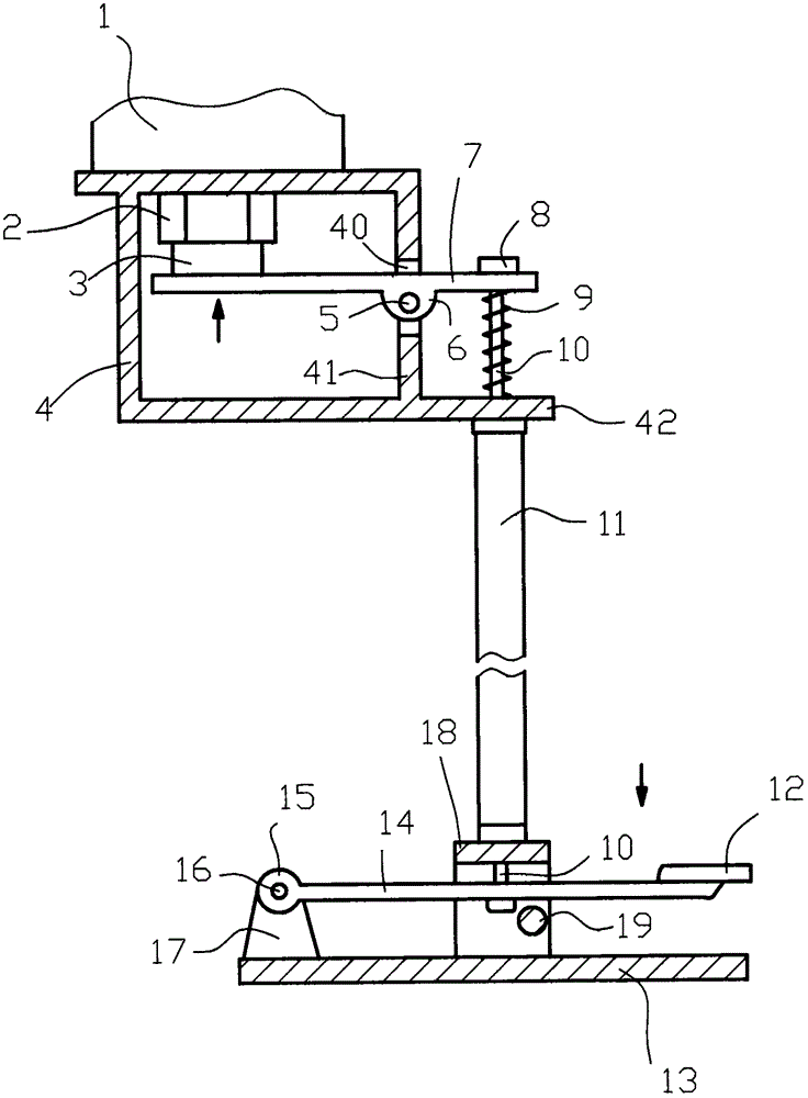
[0007] As shown in the figure, the foot-operated solenoid valve switch control mechanism consists of a solenoid valve 1, a solenoid valve connecting nut 2, a solenoid valve button 3, a control housing 4, a rocker arm 7, a spring 9, a brake line pipe 11, a foot Pedal 12, pedal base 13, locking pivot pin 19 are formed; It is characterized in that, between the end of solenoid valve 1 and solenoid valve connecting nut 2, control housing 4 is fixedly installed, and the bottom of control housing 4 is provided with Extended fins 42; the side wall 41 of the control housing 4 is prefabricated with mounting holes 40; the pivot pin 5 penetrates the pivot pin holes 6 provided on the rocker arm 7 and is fixed on both sides of the mount hole 40, and one end of the rocker arm 7 is connected to the electromagnetic The matching electromagnetic valve button 3 on the valve 1 contacts, and the other end of the rocker arm 7 is fixed with a brake core-pulling wire 10 and a brake core-pulling wire he...


PUM


Abstract

A pedal type electromagnetic valve switch control mechanism is composed of an electromagnetic valve, an electromagnetic valve connecting nut, an electromagnetic valve button, a control shell, a rocker arm, a spring, a brake cable pipe, a pedal, a pedal base and a locking shaft pin. During operation, downward operation pressure is exerted on the pedal, and the pressure is conducted to one end of the rocker arm through a pressing rod connected with the pedal and a brake core drawing wire connected with the pressing rod. The rocker arm is of a lever structure, the operation pressure is converted into reverse pressure with the shaft pin as the fulcrum, and control pressure is formed on the electromagnetic valve button through the other end of the pressing rod. Accordingly, the purpose of controlling an electromagnetic valve switch through pedaling is achieved. Under the action of the spring, mechanical actions of resetting of components connected with the pedal are achieved, and the purpose of continuous operation is achieved. Under special situations, the downward operation pressure is exerted on the pedal, the locking shaft pin capable of being freely drawn is used for fixing the pressing rod, and therefore it is guaranteed that the electromagnetic valve switch is in a controlled state for a long time.

Description

technical field [0001] The invention relates to a foot-operated electromagnetic valve switch control mechanism. Background technique [0002] Solenoid valve is an industrial equipment controlled by electromagnetic. It is an automatic basic component used to control fluid. It belongs to actuator and is not limited to hydraulic and pneumatic. It is used to adjust the direction, flow, speed and other parameters of the medium in the industrial control system. Solenoid valves can cooperate with different circuits to achieve the expected control, and the control accuracy and flexibility can be guaranteed. There are many kinds of solenoid valves. Different solenoid valves play a role in different positions of the control system. The most commonly used ones are check valves, safety valves, directional control valves, and speed regulating valves. In many fields, the start of the solenoid valve is also manually operated in combination with specific actual conditions, such as the alu...

Claims


Application Information

Patent Timeline
Patent Type & Authority Applications(China)
IPC IPC(8): F16K31/62F16K31/06
CPCF16K31/62F16K31/06
Inventor 王跃南
Owner 王跃南
Why Eureka
Try Eureka