Anti-shedding pipe joint

A technology of pipe joints and connectors, which is applied in the direction of pipes/pipe joints/fittings, hose connection devices, mechanical equipment, etc., which can solve the problems of increasing pipeline length and installation space, increasing labor intensity, and slipping of rubber hoses and pipe joints and other problems, to achieve the effect of reducing leakage and slipping accidents, high stability requirements, and good structural stability

Inactive Publication Date: 2016-11-16
浙江伟众汽车零部件有限公司
View PDF9 Cites 0 Cited by
  • Summary
  • Abstract
  • Description
  • Claims
  • Application Information

AI Technical Summary

Problems solved by technology

At normal temperature (20°C), the equipment (rubber hose) has no vibration, and the rubber hose has no internal hydraulic impact, it can maintain tightness and leak resistance; once it is exposed to high temperature (low temperature), high vibration, high Under the working environment of hydraulic impact, it is very easy to cause the relative movement of the clamp (double clamp) used to fix the rubber hose and the metal joint due to the deformation of the rubber hose, which will eventually lead to the leakage of the pipeline, and even the occurrence of rubber hose and metal joints. The case where the pipe joint slips off
[0003] One of the common solutions at present is to use a quick method to connect the rubber hose, the most commonly used is to increase the interference design, but this will increase the labor intensity of the installation process, and may damage the inner layer of the rubber hose during the installation process glue, increasing the risk of leakage
[0004] Another method is to connect the rubber hose to the pipe joint in a permanent way, such as threaded connection, but this increases the length of the pipeline and the installation space, which is difficult to use in small spaces; and the use of threaded connection directly leads to an increase in cost (can be increased by 8-15 times)

Method used


Image

  • Anti-shedding pipe joint
  • Anti-shedding pipe joint
  • Anti-shedding pipe joint

Examples


Embodiment Construction

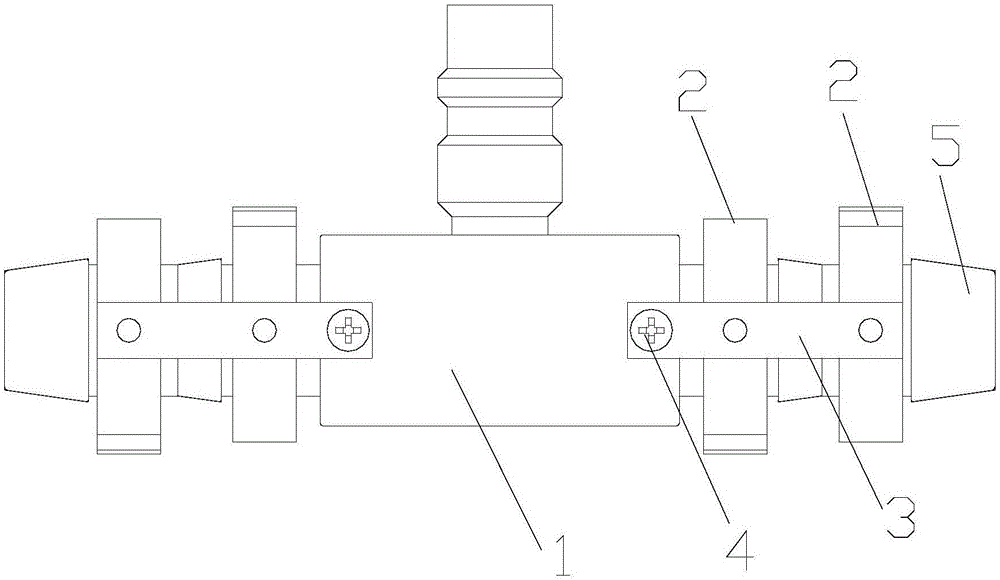
[0021] As shown in the figure, an anti-loosening pipe joint includes a pipe joint body 1, on which there are several connectors 5 for communicating with the pipeline to be connected, and the pipe joint body 1 is connected to be connected through the connectors 5 The pipeline also includes several clamp combinations for fixing the connecting head 5 and the pipeline to be connected. The clamp combination is sleeved on the connecting head 5, and there is a gap between the inner wall of the clamp combination and the outer wall of the connecting head 5, so as to be installed. connecting pipes;

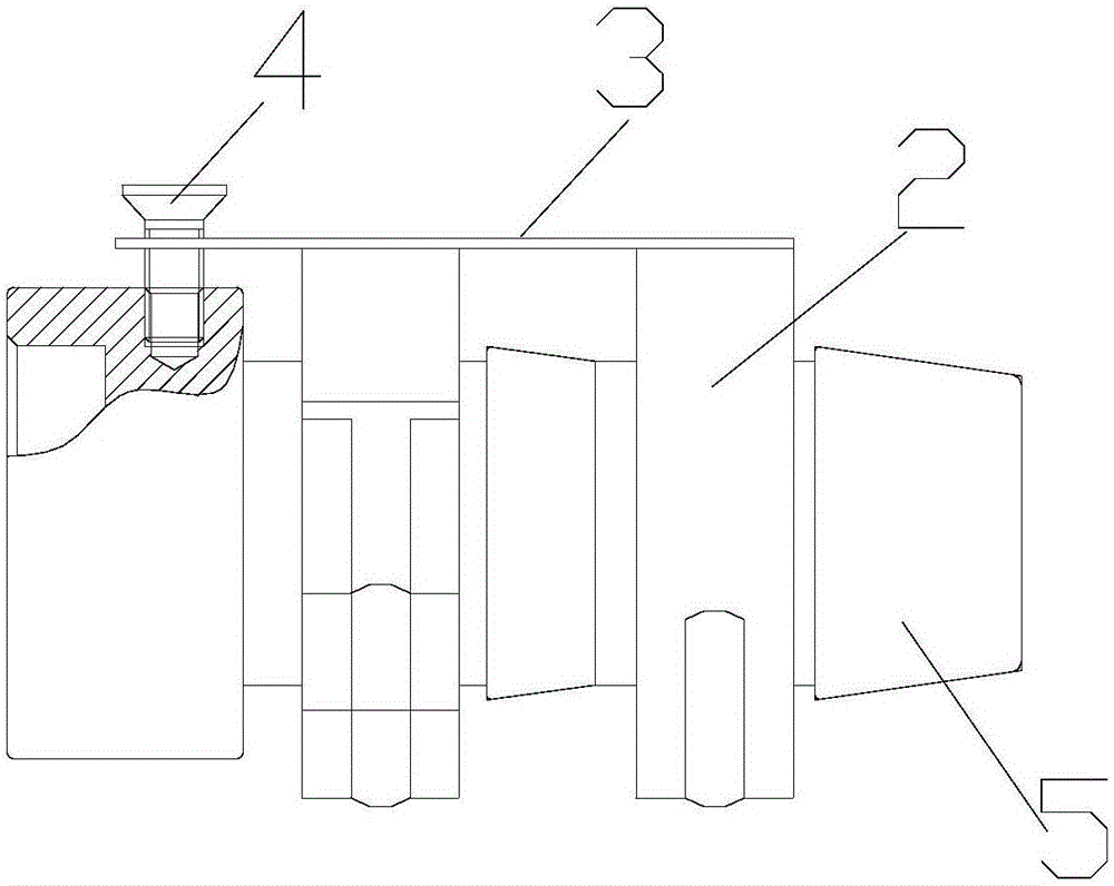
[0022] The clamp combination includes several clamps 2 arranged in parallel, and the adjacent clamps 2 in each clamp combination are fixedly connected by a connecting piece 3; and one end of the connecting piece 3 extends horizontally to the pipe joint body 1, and passes through The fixing device is fixed on the pipe joint body 1;

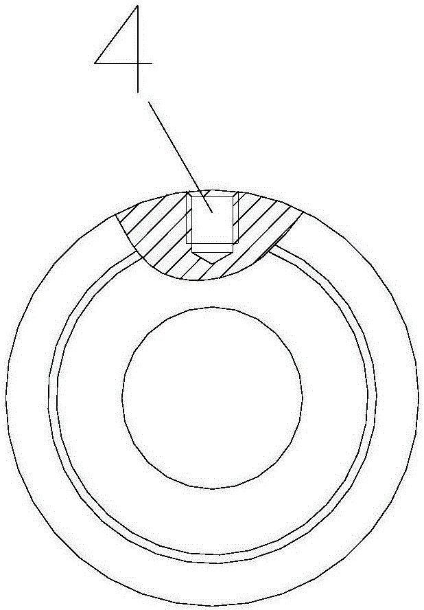
[0023] The fixing device includes a screw hole and a scre...


PUM


Abstract

The invention discloses an anti-shedding pipe joint. The anti-shedding pipe joint comprises a pipe joint body, wherein a plurality of connectors communicated with pipelines to be connected are arranged on the pipe joint body; the anti-shedding pipe joint is characterized by further comprising a plurality of clamp hoop assemblies used for fixing the connectors with the pipelines to be connected; the clamp hoop assemblies sleeve the connectors; gaps are reserved between the inner walls of the clamp hoop assemblies and the outer walls of the connectors and are used for mounting the pipelines to be connected; each clamp hoop assembly comprises a plurality of parallel clamp hoops; adjacent clamp hoops in each clamp hoop assembly are fixedly connected via a connection part; one end of the connection part horizontally extends to the pipe joint body and is fixed on the pipe joint body via a fixing device. Through the anti-shedding pipe joint, the clamp hoops are fixed on the pipe joint body via bolts; the clamp hoops are fixed in the axial position of the pipe joint body; the constraining force applied to rubber hoses is improved; effective contact and action force between the inner surfaces of the rubber hoses and the connectors can be still retained; the occurrence of leakage and shedding accidents can be effectively reduced.

Description

technical field [0001] The invention relates to an anti-loosening pipe joint. Background technique [0002] In an environment with a working temperature of -40-140°C, due to equipment design or installation requirements, the rubber hose used to transport refrigerant has T-shaped or cross-shaped forked connections. In actual use, quick connectors are often used to match quick cards. The hoop realizes the connection between 2 or more rubber hoses. It is mainly to offset the slipping force of the rubber hose by the friction force between the rubber hose and the quick connector tube core after the rubber hose and the quick connector are tightened by the quick clamp. At normal temperature (20°C), the equipment (rubber hose) has no vibration, and the rubber hose has no internal hydraulic impact, it can maintain tightness and leak resistance; once it is exposed to high temperature (low temperature), high vibration, high Under the working environment of hydraulic impact, it is ver...

Claims


Application Information

Patent Timeline
Patent Type & Authority Applications(China)
IPC IPC(8): F16L33/02
CPCF16L33/02
Inventor 陈志源俞伟萍
Owner 浙江伟众汽车零部件有限公司
Why Eureka
Try Eureka