Pipeline monitoring system

A monitoring system and pipeline technology, applied in the electronic field, can solve the problems of pipeline leakage, low positioning accuracy, poor real-time monitoring, etc., to achieve the effect of monitoring leakage and improving positioning accuracy

Active Publication Date: 2016-11-16
倪晨钧
View PDF15 Cites 8 Cited by
  • Summary
  • Abstract
  • Description
  • Claims
  • Application Information

AI Technical Summary

Problems solved by technology

[0004] The technical problem to be solved by the present invention is to overcome the defects of poor real-time performance and low positioning accuracy of pipeline leakage monitoring in the prior art

Method used


Image

  • Pipeline monitoring system
  • Pipeline monitoring system
  • Pipeline monitoring system

Examples


Embodiment 1

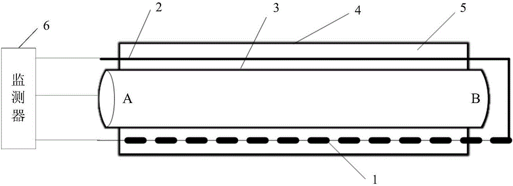
[0033] This embodiment provides a pipeline monitoring system, such as figure 1 shown. The pipeline to be monitored is a metal pipeline, and a pipeline insulation layer 5 and a pipeline shell 4 are arranged on the outer layer of the pipeline steel pipe 3 . Between the two ends A and B of the pipeline steel pipe 3 is the monitored pipeline part. Pipe insulation layer 5 adopts insulating material, and foam can be used. In the insulation layer 5 of the pipeline to be monitored, the sensing line 1 and the feedback line 2 are pre-embedded along the axial direction of the pipeline, and one end of the sensing line 1 and the feedback line 2 is connected outside the B end of the pipeline steel pipe 3 .

[0034] The pipeline monitoring system includes a sensing line 1 , a feedback line 2 and a monitor 6 . The sensing line 1 is wrapped with an insulating layer, and the insulating layer is distributed with through holes along the length direction to expose the sensing line 1. When the m...

Embodiment 2

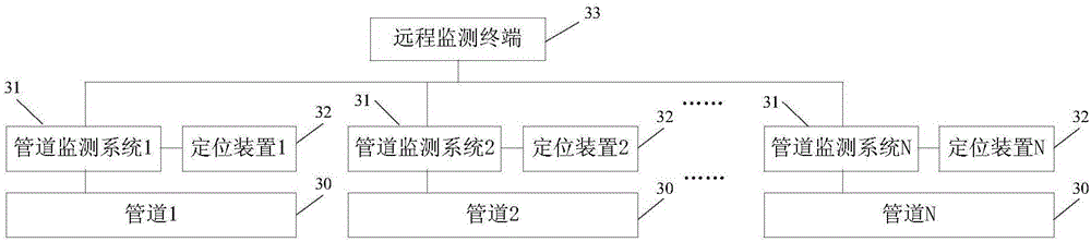
[0041] This embodiment provides a pipeline network monitoring system, the structural diagram of the pipeline network monitoring system is as follows image 3 As shown, it includes a plurality of pipeline monitoring systems 31 as described in Embodiment 1, a plurality of positioning devices 32 and a remote monitoring terminal 33 .

[0042] The pipeline network monitoring system includes N pipelines 30, and each pipeline is provided with N pipeline monitoring systems 31 for monitoring the leakage status of each pipeline. At the N pipeline monitoring systems, N positioning devices 32 are correspondingly provided for determining the position of each pipeline monitoring system.

[0043] The remote monitoring terminal 33 is connected to N pipeline monitoring systems 31 and N positioning devices 32 respectively, and is used to receive the leakage status of each pipeline and the location of the corresponding pipeline monitoring system. As a specific implementation, the pipeline leaka...

Embodiment 3

[0046] This embodiment provides a pipeline leak detection method, the flow chart of the method is as follows Figure 4 As shown, it specifically includes the following steps:

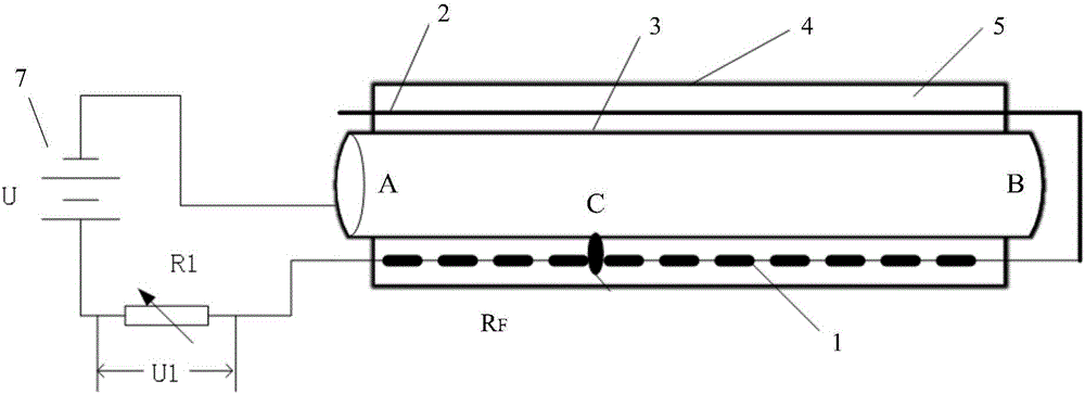
[0047] S1: Obtain the first voltage and the second voltage from the leak point on the detection line in the insulation layer of the detected pipeline to the two ends of the pipeline. As a specific implementation, such as Figure 5 As shown, first obtain the first voltage U2 from the leakage point C on the detection line in the insulation layer 5 of the pipeline to be detected, that is, the leakage point C on the sensing line 1, to the A end of the pipeline steel pipe; Image 6 As shown, the second voltage U3 from the leakage point C on the detection line in the thermal insulation layer 5 of the pipeline to be detected, that is, on the sensing line 1 to the end of the pipeline steel pipe B, is obtained.

[0048] S2: Calibrate the actual length of the detected pipeline according to the first voltage and...


PUM


Abstract

The invention provides a pipeline monitoring system which comprises a sensing line, a feedback line and a monitor. When it is monitored that liquid is leaked at any position of a monitored pipeline, the leaked liquid in a heat-preserving layer of the pipeline enables the monitored pipeline, the sensing line and the monitor to communicate to form a loop, and the monitor is used for determining whether the monitored pipeline leaks the liquid or not according to a voltage value between the sensing line and the monitored pipeline. The system can find out leakage of a heat supply pipeline in time, by means of holes regularly distributed in an insulating layer of the sensing line, leakage points of the pipeline are located accurately, the locating precision is improved, and the leakage situation of the pipeline is effectively monitored.

Description

technical field [0001] The invention relates to the field of electronic technology, in particular to a pipeline monitoring system. Background technique [0002] With the advancement of urbanization, the demand for central heating in cities is increasing, and the laying network of direct buried heating pipelines is also gradually expanding. With the long-term operation of heating pipelines, due to pipeline aging, geological changes, poor construction and other reasons, it is easy to cause leakage of directly buried pipelines. Therefore, it is very important to monitor the leakage of each pipeline in the pipeline network in real time and accurately locate the leakage point of the pipeline. [0003] At present, there are relatively few automatic detection applications for pipeline monitoring. Most heating pipelines still use manual inspection methods with outdated technology. It is difficult to detect early hidden pipeline leaks in time and the alarm is not timely. heating le...

Claims


Application Information

Patent Timeline
Patent Type & Authority Applications(China)
IPC IPC(8): F24D19/10G01M3/18
CPCF24D19/1009G01M3/182F24D2220/04
Inventor 倪晨钧
Owner 倪晨钧
Why Eureka
Try Eureka