Full-automatic high-sensitivity pipe network leakage monitoring sensor

A technology for monitoring sensors and sensitive tubes, which is applied in the field of sensors, can solve problems such as complex structures, and achieve the effects of low cost, good precision and reliability

Active Publication Date: 2021-10-22
SANMEN NUCLEAR POWER CO LTD
View PDF13 Cites 0 Cited by
  • Summary
  • Abstract
  • Description
  • Claims
  • Application Information

AI Technical Summary

Problems solved by technology

The disadvantage of this solution is that the structure is complex, and in order to detect the working flow, another large flow sensor needs to be added

Method used


Image

  • Full-automatic high-sensitivity pipe network leakage monitoring sensor
  • Full-automatic high-sensitivity pipe network leakage monitoring sensor
  • Full-automatic high-sensitivity pipe network leakage monitoring sensor

Examples


Embodiment 1

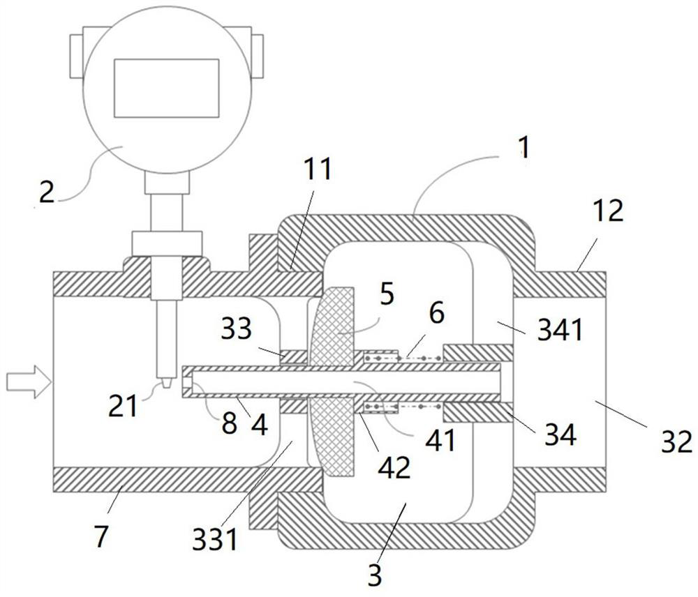
[0032] A kind of fully automatic high-sensitivity pipe network leakage monitoring sensor of the present invention, such as figure 1 As shown, it includes a check valve body 1 and a sensor body 2. A medium channel 3 is provided inside the check valve body 1. The two ends of the medium channel 3 are respectively a medium inlet and a medium outlet 32. The center position of the medium inlet and the medium outlet 32 ​​is A first valve seat 33 and a second valve seat 34 coaxially arranged with the check valve body 1 are provided respectively, and a valve core 4 is interspersed on the first valve seat 33 and the second valve seat 34, and a valve core 4 is sleeved on the valve core 4. A spring 6 is installed between the valve core 4 and the second valve seat 34. The valve core 4 is guided by the first valve seat 33 and the second valve seat 34. Under the action of the spring 6, the valve disc 5 is driven to move and close the medium inlet. The check valve body 1 is installed on the p...

Embodiment 2

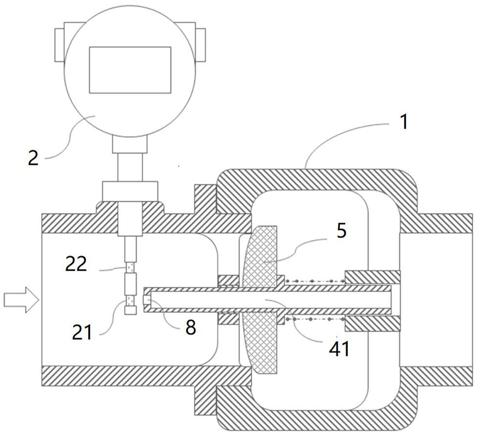
[0045] refer to figure 2 , in order to better sample the flow field, add a probe on the basis of implementation one, the newly added probe is the second probe 22, and the newly added second probe 22 is set at the position between the first probe 21 and the pipe wall superior.

[0046]The flow velocity signals of the two probes are collected separately, and then comprehensively calculate and output the flow digital value, providing two sampling values ​​of the internal flow field (radial curve) of the pipeline 7, and the flow rate can be calculated by fitting the flow field curve. The flow rate can be obtained through real-time table lookup; the lookup table is obtained in advance through fitting calculation or actual flow test.

Embodiment 3

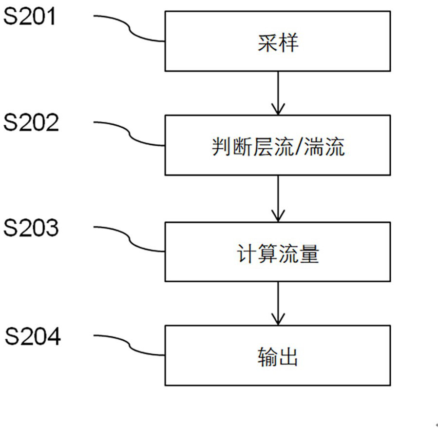
[0048] refer to image 3 , the sensor body 2 also has a single-chip microcomputer, which executes as image 3 Data processing steps shown. Proceed as follows:

[0049] S201: Sampling, sampling the flow velocity signal of the probe 21, the sampling accuracy is 12 bits, and the sampling frequency is 100 Hz;

[0050] S202: judge laminar flow / turbulent flow, that is, calculate the noise level for the original signal, and judge laminar flow / turbulent flow accordingly;

[0051] S203: calculate flow rate;

[0052] S204: outputting, that is, providing the flow data to an external device.

[0053] The above steps are executed cyclically.

[0054] Under water spraying conditions, the fire hose is always in a turbulent state (Reynolds number is much greater than 2300), but usually because the absolute value of the leakage flow is very small, even if a high flow rate is formed on the probe, it is still a laminar flow. The step S202 of judging laminar / turbulent flow S202 is based on ...


PUM


Abstract

The invention relates to a full-automatic high-sensitivity pipe network leakage monitoring sensor, and belongs to the technical field of sensors. The full-automatic high-sensitivity pipe network leakage monitoring sensor comprises a check valve body and a sensor body, wherein a valve clack capable of freely moving in the medium flowing-in and flowing-out direction is arranged in the check valve body, a valve element synchronously moving along with the valve clack is arranged on the valve clack, a channel is formed in the valve element, a channel inlet of the channel is provided with a flow speed gain part, and the sensor body is provided with a probe close to the flow speed gain part. The full-automatic high-sensitivity pipe network leakage monitoring sensor has the function of detecting the working flow and the leakage flow; during water spraying, the channel inlet is far away from the probe, the sensor body works under the default working condition, and an output signal is the actual flow; and at ordinary times, the channel inlet is close to the probe, leaked micro flow has a high flow speed on the probe through the acceleration effect of the channel and the flow speed gain part of the channel inlet, at the moment, the output flow of the sensor body is obtained by multiplying the leakage flow by the flow speed gain, and therefore the leakage condition is monitored.

Description

technical field [0001] The invention relates to a fully automatic high-sensitivity pipe network leakage monitoring sensor, which belongs to the technical field of sensors. Background technique [0002] Current leakage monitoring, the method adopted in the prior art is to set a check valve loaded by an elastic element and a small pipe diameter bypass in parallel on the main line, and a sensor that can detect a small flow is set on the bypass; In the state of spraying water, the water flow mainly flows through the check valve; in the state of non-spraying water, due to the elastic blocking effect of the one-way valve, the leakage water mainly flows through the bypass; in this way, a special leakage flow detection can be formed device. The disadvantage of this solution is that the structure is complex, and in order to detect the working flow, another large flow sensor needs to be added. Contents of the invention [0003] The technical problem to be solved by the present inv...

Claims


Application Information

Patent Timeline
Patent Type & Authority Applications(China)
IPC IPC(8): F17D5/02F17D5/00F16K15/06
CPCF17D5/02F17D5/00F16K15/06
Inventor 夏恩亮王振国陈志鹏杜耀东陈岑凯沈哲王京升张松周忠秋乔思豫姚明奇刘慧超
Owner SANMEN NUCLEAR POWER CO LTD
Why Eureka
Try Eureka