Vacuum boiler and method, device and system for conducting vacuum exhausting on vacuum boiler
A vacuum boiler and vacuum exhaust technology, which is applied in the field of vacuum boiler and vacuum boiler exhaust, can solve the problems of increasing the production cost of vacuum boilers, heat damage, and potential safety hazards, so as to achieve rapid response, save production costs, and reduce safety. hidden effect
- Summary
- Abstract
- Description
- Claims
- Application Information
AI Technical Summary
Problems solved by technology
Method used
Image

Examples
Embodiment 1
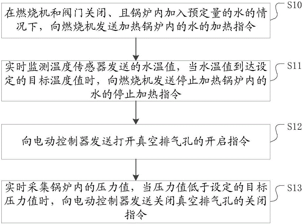
[0034] figure 1 A flow chart of a method for vacuuming a vacuum boiler provided by the present invention. like figure 1 As shown, the method of evacuating the vacuum boiler includes:
[0035] Step S10: When the burner and the valve are closed and a predetermined amount of water is added to the boiler, a heating command for heating the water in the boiler is sent to the burner.
[0036] Turn off the burner and valve, add a predetermined amount of water to the boiler, and the burner starts to heat the water in the boiler. While the burner is heating the water in the boiler, the process proceeds to step S11. Among them, there is a sight glass in the middle position of the boiler wall. In order to facilitate observation, the predetermined amount is 1 / 2 of the sight glass. It should be specially pointed out that the predetermined amount in the present invention is not limited to this value.
[0037] Step S11: Monitor the water temperature value sent by the temperature sensor in...
Embodiment 2
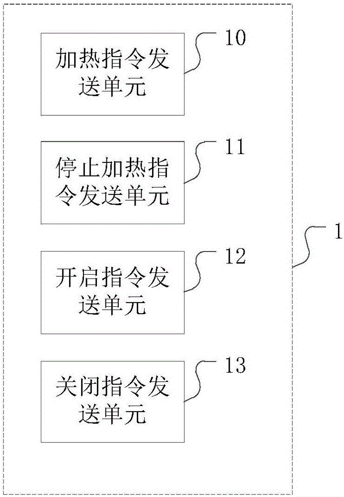
[0046] figure 2 It is a structural diagram of a device for evacuating a vacuum boiler provided by the present invention. like figure 2 As shown, the device 1 for vacuuming a vacuum boiler includes:
[0047] The heating command sending unit 10 is configured to send a heating command to the burner to heat the water in the boiler when the burner and the valve are closed and a predetermined amount of water is added to the boiler.
[0048] The heating command sending unit 10 sends a heating command to the burner only when water is added to the boiler, which avoids the dry burning of the boiler, increases the safety of operation, and prolongs the service life of the boiler.
[0049] The heating stop command sending unit 11 is used to monitor the water temperature value sent by the temperature sensor in real time, and when the water temperature value reaches the set target temperature value, send a heating stop command to the burner to stop heating the water in the boiler.
[00...
Embodiment 3
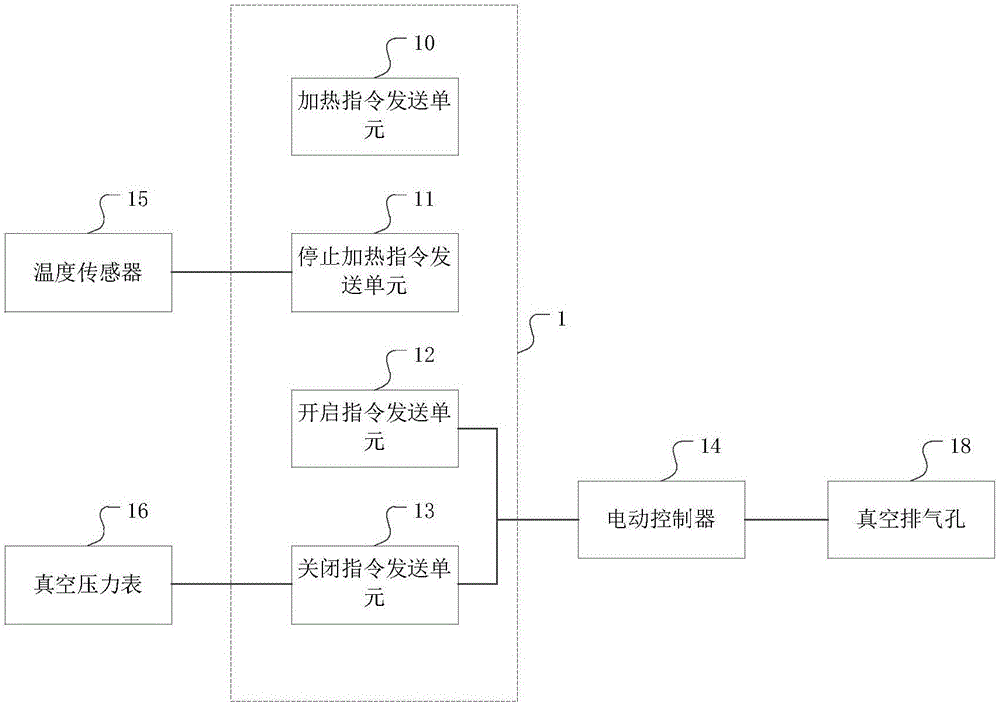
[0058] On the basis of the second embodiment, image 3 The structure diagram of a system for evacuating a vacuum boiler provided by the present invention. like image 3 As shown, in addition to the device 1 for evacuating the vacuum boiler in the second embodiment, the system for evacuating the vacuum boiler also includes: a temperature sensor 15 connected to the device 1 for evacuating the vacuum boiler, a vacuum pressure gauge 16, a vacuum exhaust hole 18 and electric controller 14.
[0059] The temperature sensor 15 is arranged on the boiler wall and is used to measure the water temperature value of the water in the boiler.
[0060] The vacuum pressure gauge 16 is arranged on the boiler wall and is used to measure the pressure value in the boiler.
[0061] The vacuum exhaust hole 18 is arranged on the boiler wall, and is used to discharge the steam in the boiler.
[0062] The electric controller 14 is connected to the vacuum vent 18 for controlling the opening and closi...
PUM
 Abstract
Description
Claims
Application Information
 - R&D
- Intellectual Property
- Life Sciences
- Materials
- Tech Scout
- Unparalleled Data Quality
- Higher Quality Content
- 60% Fewer Hallucinations
Browse by: Latest US Patents, China's latest patents, Technical Efficacy Thesaurus, Application Domain, Technology Topic, Popular Technical Reports.
© 2025 PatSnap. All rights reserved.Legal|Privacy policy|Modern Slavery Act Transparency Statement|Sitemap|About US| Contact US: help@patsnap.com