Camera optical axis direction calculation method based on high-precision posture information

A technology of optical axis pointing and attitude information, which is applied in testing optical performance and other directions, can solve the problem that high-precision optical axis pointing information is difficult to obtain accurately, and achieve the effect of improving imaging capabilities

Active Publication Date: 2016-11-16
SHANGHAI AEROSPACE CONTROL TECH INST
View PDF7 Cites 25 Cited by
  • Summary
  • Abstract
  • Description
  • Claims
  • Application Information

AI Technical Summary

Problems solved by technology

[0004] But at the same time, the use of scanning mirrors also brings some new influences to the imaging process of remote sensing cameras. Affected by factors such as the thermal deformation of the earth's orbit, platform control errors, and scanning mechanism pointing deviations, th

Method used


Image

  • Camera optical axis direction calculation method based on high-precision posture information
  • Camera optical axis direction calculation method based on high-precision posture information
  • Camera optical axis direction calculation method based on high-precision posture information

Examples


Embodiment Construction

[0023] The invention will be described in more detail hereinafter with reference to the accompanying drawings showing embodiments of the invention. However, this invention may be embodied in many different forms and should not be construed as limited to the embodiments set forth herein.

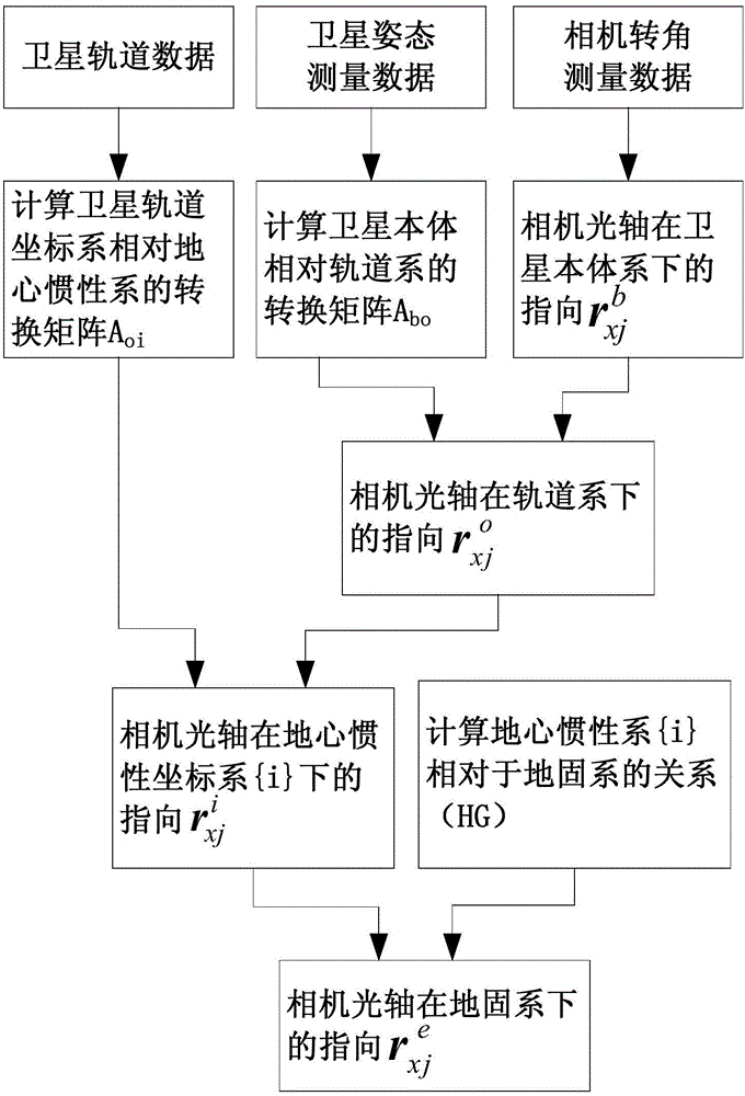
[0024] Such as figure 1 As shown, the present invention provides a camera optical axis pointing calculation method based on high-precision attitude information, including the following process:

[0025] 1. Calculate the direction of the optical axis of the scanning camera under the satellite system {b}

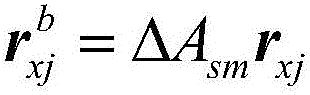
[0026] Use the camera detector center point r sm As the input of the signal, by deriving r sm After scanning and rotating, the output light r in the camera body coordinate system (consistent with the measurement coordinate system) is obtained xj , with r xj To describe the relationship between the camera rotation angle measurement information and the optical axis pointing:

[0027] r ...


PUM


Abstract

The invention provides a camera optical axis direction calculation method based on high-precision posture information, and the method comprises the steps: calculating the orientation (shown in the description) of a camera optical axis in a rail coordinate system according to the orientation (shown in the description) of a scanning camera optical axis in a satellite system {b} and the conversion matrix Abo of the satellite system {b} relative to the rail coordinate system {o}; calculating the orientation (shown in the description) of the camera optical axis in an inertial coordinate system {i} according to the orientation (shown in the description) of the camera optical axis in the rail coordinate system {o} and a conversion matrix Aoi of the rail coordinate system {o} relative to the inertial coordinate system {i}; calculating the orientation (shown in the description) of the camera optical axis in an earth-fixed reference coordinate system according to the orientation (shown in the description) of the camera optical axis in the inertial coordinate system {i} and a conversion matrix (HG) of the inertial coordinate system {i} relative to the earth-fixed reference coordinate system. The method can achieve the real-time calculation on the ground and correct the orientation of the optical axis, also can enable the information of a rail and the earth-fixed reference coordinate system on the ground to be stored on a satellite in advance so as to autonomously carry out real-time calculation and correct the orientation of the optical axis, and can improve the imaging capability of the satellite in a simple mode.

Description

technical field [0001] The invention relates to satellite optical axis pointing technology, in particular to a camera optical axis pointing calculation method based on high-precision attitude information. Background technique [0002] In recent years, aerospace optical remote sensing technology has achieved great development. In order to make remote sensing instruments have both high ground resolution and large observation range, moving scanning mirrors are often used to enable remote sensing cameras to conduct detailed observations of ground targets at different locations. . [0003] The scanning imager IMAGER installed on the GOES-I / M satellite of the United States adopts the way of scanning east and west with a pendulum mirror. The TM (Main Mapper) on the American Landsat-4 and 5 satellites is a sweeping multi-spectral scanning radiometer. The HRG (High Resolution Geometry) camera on the French SPOT-5 satellite uses a pointing mirror mechanism to obtain oblique viewing ...

Claims


Application Information

Patent Timeline
IPC IPC(8): G01M11/02
CPCG01M11/02
Inventor 谢任远马雪阳何益康余维
Owner SHANGHAI AEROSPACE CONTROL TECH INST
Why Eureka
Try Eureka