
A Method for Identification and Correction of Total Error Parameters of Three-axis Magnetometers Independent of Geomagnetic Field Quantity

An error parameter and error correction technology, applied in the field of three-axis magnetometer full error parameter identification and correction, can solve the problem of losing the economy of the identification and correction method, increase the cost of identification and correction system, and cannot realize the full function of the magnetometer. Error parameter identification and correction

Active Publication Date: 2019-02-26
HARBIN ENG UNIV
View PDF8 Cites 0 Cited by
  • Summary
  • Abstract
  • Description
  • Claims
  • Application Information

AI Technical Summary

Problems solved by technology

[0004] The current magnetometer error identification and correction methods mainly have two major limitations: (1) only one or two of the magnetometer errors are corrected, and the identification and correction of the full error parameters of the magnetometer cannot be realized; (2) even To be able to identify and correct the full error parameters of the magnetometer, it must also be equipped with external auxiliary measurement equipment, such as a scalar magnetometer and attitude measuring equipment for measuring the local magnetic field value, which increases the use cost of the identification and correction system and loses The economy of the identification and correction method

Method used


Image

  • A Method for Identification and Correction of Total Error Parameters of Three-axis Magnetometers Independent of Geomagnetic Field Quantity
  • A Method for Identification and Correction of Total Error Parameters of Three-axis Magnetometers Independent of Geomagnetic Field Quantity
  • A Method for Identification and Correction of Total Error Parameters of Three-axis Magnetometers Independent of Geomagnetic Field Quantity

Examples


Embodiment Construction

[0048] The present invention will be described in detail below in conjunction with specific embodiments.

[0049] Step 1. Establish a three-axis magnetometer full-error magnetic measurement model:

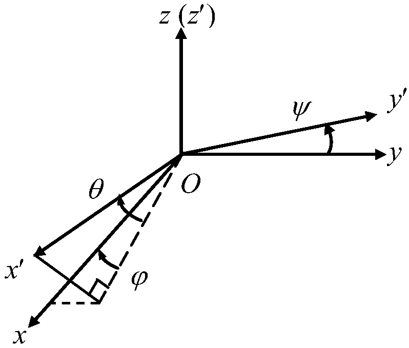
[0050] Generally speaking, the three axes of the sensor coordinate system Ox'y'z' where the magnetometer is located are non-orthogonal in pairs. Establish a spatial orthogonal coordinate system Oxyz on the basis of the sensor coordinate system, such as figure 1 As shown, the Oz axis coincides with the Oz' axis, the coordinate plane yOz and y'Oz' are coplanar, the angle between the Oy' axis and the Oy' axis is ψ, and the Ox axis is determined by the Oy axis and the Oz axis. The direction of the Ox' axis can be determined by the angle θ and to represent, where θ is the angle between the Ox′ axis and the xOy plane, is the angle between the projection of the Ox' axis on the xOy plane and the Ox axis, that is, θ, ψ describes the three-axis space non-orthogonal relationship of the...


PUM


Abstract

The invention provides a triaxial magnetometer total-error parameter identification and correction method independent from an earth magnetic field quantity. By use of modular invariance of an earth magnetic field, total-error parameters of a triaxial magnetometer are identified through earth magnetic field vector measurement data under different attitudes, based on this, an error corrector is constructed, total errors of the triaxial magnetometer are corrected by use of the constructed error corrector, and a detected magnetic field after correction is obtained. The method solves the problem of incapability total-error correction of the triaxial magnetometer due to incapability of identification of the total-error parameters of the triaxial magnetometer in the absence of the earth magnetic field quantity in the prior art; and at the same time, an additional earth magnetic field measurement device is unnecessary, and an additional attitude measurement device is also unnecessary for providing accurate external attitude information. The method further identifies all triaxial magnetometer errors, is high in identification precision, does not need auxiliary devices for measuring the earth magnetic field and the attitudes, simplifies the correction apparatus of the triaxial magnetometer and decreases the cost of a magnetic field measurement system.

Description

technical field [0001] The invention relates to a method for measuring the earth's magnetic field, in particular to a method for identifying and correcting full error parameters of a three-axis magnetometer that does not depend on the amount of the earth's magnetic field. Background technique [0002] The geomagnetic field is the inherent physical field of the earth and is closely related to human life. It has important applications in the fields of earth science, aerospace, resource exploration and earthquake prediction. The three-axis magnetometer is an important instrument for measuring the three components of the geomagnetic field and its modulus. Due to the imperfect manufacturing technology and installation process, the three-axis magnetometer has non-orthogonality of the three measurement axes, sensitivity deviation between the axes and zero offset error of the three measurement axes; these instrument errors not only affect the measured magnetic field three The measu...

Claims


Application Information

Patent Timeline
Patent Type & Authority Patents(China)
IPC IPC(8): G01R35/00G01V13/00
CPCG01R35/005G01V13/00
Inventor 黄玉武立华姜海丽吕振川齐瑞云
Owner HARBIN ENG UNIV
Learn More