
Coil mold structure

A mold and coil technology, applied in the field of coil mold structure, can solve problems such as difficulty in mold storage, coil deformation, and a large number of molds, and achieve the effects of low manufacturing and use costs, preventing casting deformation, and solving storage problems

Active Publication Date: 2016-11-16
广州中车骏发电气有限公司
View PDF5 Cites 0 Cited by
  • Summary
  • Abstract
  • Description
  • Claims
  • Application Information

AI Technical Summary

Problems solved by technology

[0002] In the process of manufacturing transformer coils, due to the different dimensions of different coils, dry-type transformer coils require specific coils to manufacture corresponding molds. In the existing hard mold mold structure, the inner mold is an integral hard structure, and the outer mold The mold is relatively thick and is used with the lower limit plate, so this type of mold will not be easily deformed, and the cast coil can ensure good molding quality, but it will lead to a large number of molds, and there is a problem of difficult storage of molds
The mold structure of the soft mold can solve the problem of mold storage due to the large number of rigid molds because of its softness. However, the existing mold structure of the soft mold is easy to deform due to the softness of the inner and outer molds, resulting in the casting of the coil. Deformation will occur, resulting in poor molding quality and unable to meet the requirements of use

Method used


Image

  • Coil mold structure
  • Coil mold structure
  • Coil mold structure

Examples


Embodiment Construction

[0026] Embodiments of the present invention are described in detail below:

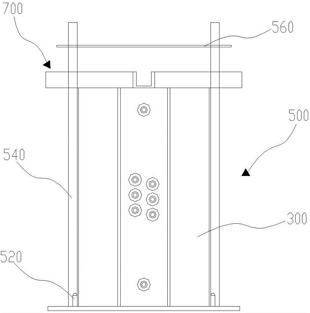
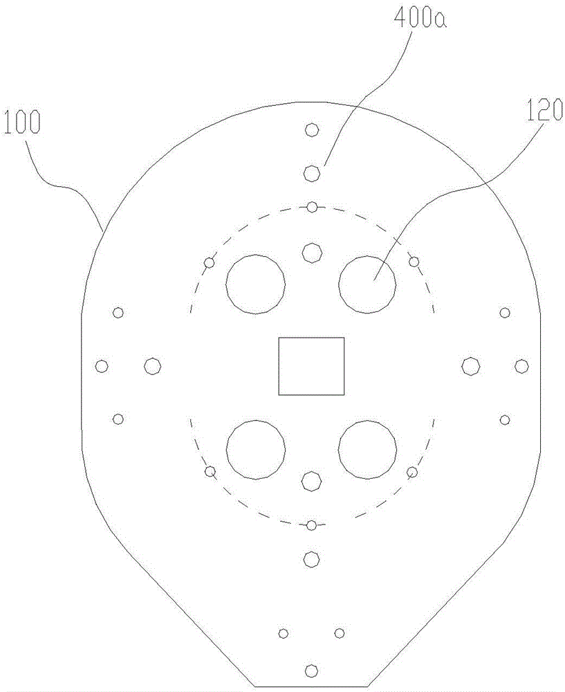
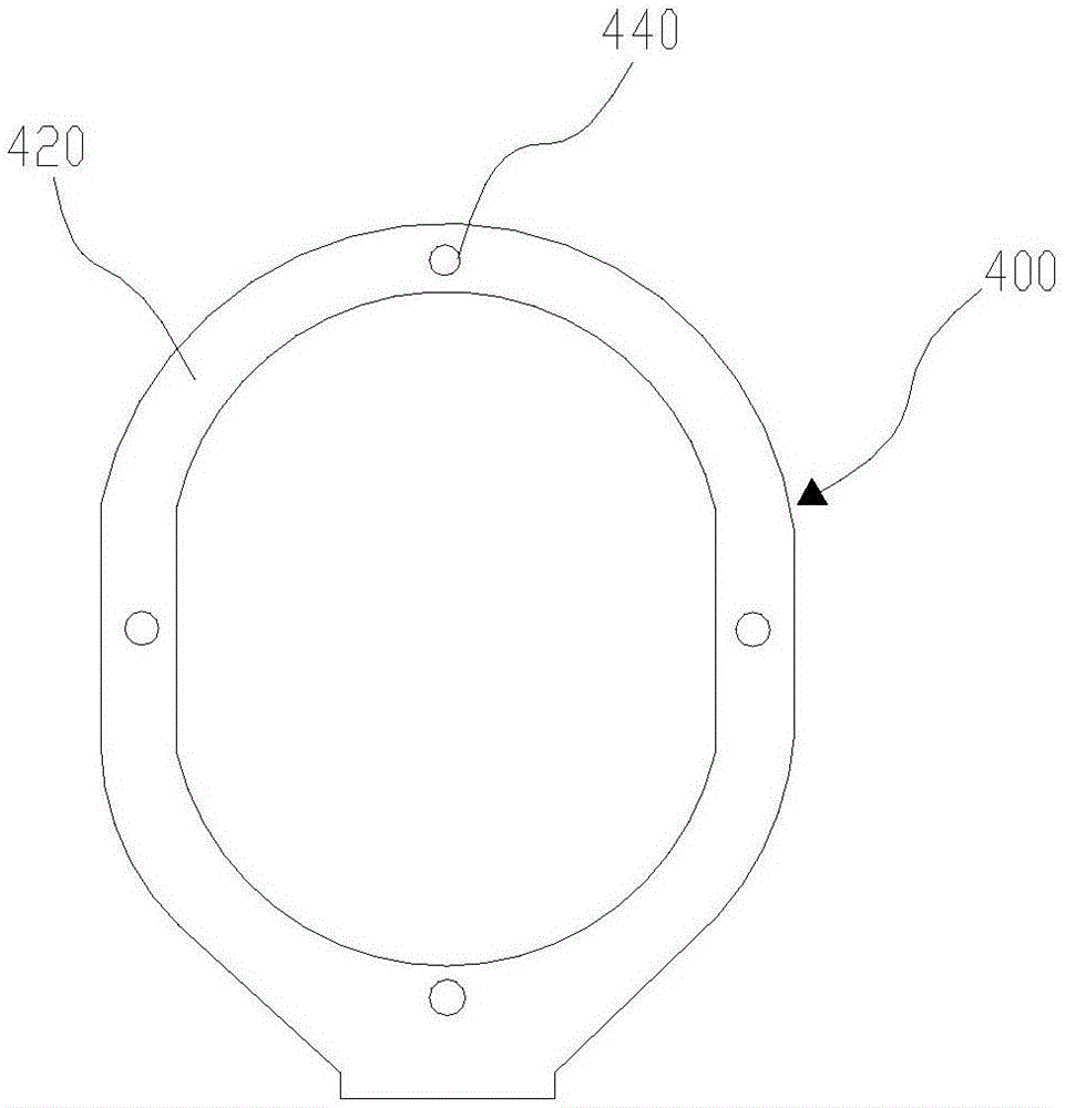
[0027] Such as Figure 1 to Figure 7 As shown, a coil mold structure includes a casting base plate 100, an inner mold 200 and an outer mold 300 with soft mold characteristics, a limiting plate assembly 400 and an outer mold limiting mechanism 500, and the casting base plate 100 has a limiting plate installed part, the limit plate assembly 400 is set on the limit plate installation part, the inner mold 200 and the outer mold 300 are both set on the pouring bottom plate 100, and the outer mold 300 is set on the inner mold The mold 200 is outside, and a pouring chamber is formed between the inner mold 200 and the outer mold 300 , and the outer mold limiting mechanism 500 is fastened on the outer mold 300 outside.

[0028] The above-mentioned coil mold structure is made by making the inner mold 200 and the outer mold 300 as a soft mold structure, and then both the inner mold 200 and the outer mold 300 ar...


PUM


Abstract

The invention discloses a coil mold structure comprising a pouring base plate, an inner mold and an outer mold with characteristics of a soft mode , a limiting plate component and an outer mold limiting mechanism, wherein the pouring base plate is provided with a limiting plate installation portion, the limiting plate component is arranged at the limiting plate installation portion, both the inner mold and the outer mold are arranged on the pouring base plate, the outer mold is sleeved on the inner mold, a pouring cavity is formed between the inner mold and the outer mold, and the outer mold limiting mechanism is installed on the outer side of the outer mold in a buckling manner. Therefore, a storage problem can be solved, meanwhile, a coil can also be prevented from deforming during pouring and good molding quality can be ensured, and the coil mold structure is low in production and usage costs.

Description

technical field [0001] The invention relates to the technical field of coil mold manufacturing, in particular to a coil mold structure. Background technique [0002] In the process of manufacturing transformer coils, due to the different dimensions of different coils, dry-type transformer coils require specific coils to manufacture corresponding molds. In the existing hard mold mold structure, the inner mold is an integral hard structure, and the outer mold The mold is relatively thick and is used with the lower limit plate, so this type of mold will not be easily deformed, and the cast coil can ensure good molding quality, but it will lead to a large number of molds, and there is a problem of difficult storage of molds. The mold structure of the soft mold can solve the problem of mold storage due to the large number of rigid molds because of its softness. However, the existing mold structure of the soft mold is easy to deform due to the softness of the inner and outer molds...

Claims


Application Information

Patent Timeline
IPC IPC(8): H01F41/04B29C39/26
CPCB29C39/26H01F41/04
Inventor 梁应乐
Owner 广州中车骏发电气有限公司
Features
  • Generate Ideas
  • Intellectual Property
  • Life Sciences
  • Materials
  • Tech Scout
  • Unparalleled Data Quality
  • Higher Quality Content
  • 60% Fewer Hallucinations
Learn More