A high efficiency commutation circuit

A commutation circuit and current-passing technology, which is applied in the direction of electronic commutator, single-phase motor control, etc.

Active Publication Date: 2016-11-16
ABB (SCHWEIZ) AG
View PDF10 Cites 2 Cited by
  • Summary
  • Abstract
  • Description
  • Claims
  • Application Information

AI Technical Summary

Problems solved by technology

Thyristors, on the other hand, are not turn-off semiconductor devices

Method used


Image

  • A high efficiency commutation circuit
  • A high efficiency commutation circuit
  • A high efficiency commutation circuit

Examples


Embodiment Construction

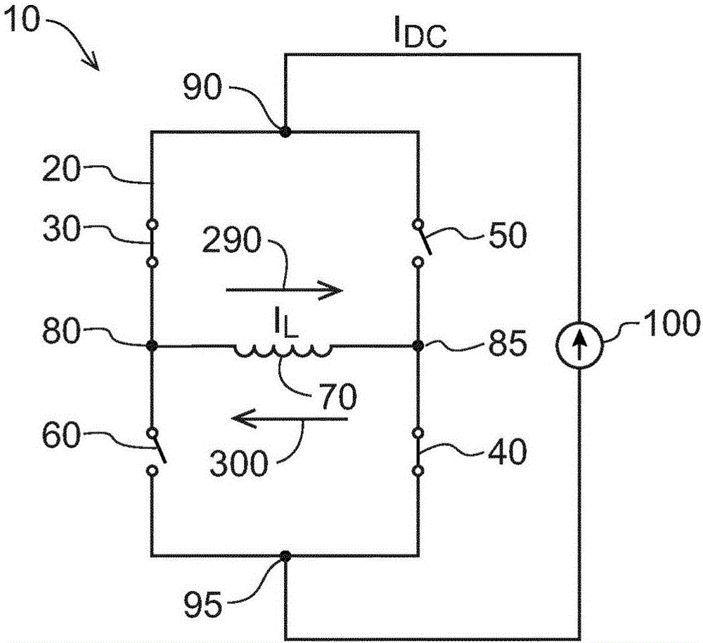
[0027] All embodiments of the invention disclosed herein include those corresponding to figure 1 In the subcircuits shown in , the only difference is that at least some of the main switches 30 , 40 , 50 , 60 according to the disclosed embodiments of the invention are implemented as thyristors. In the following description, an H-bridge 20 having four main switches 30, 40, 50, 60, a coil 70 connected to the output terminals 80, 85 of the H-bridge 20, and an input terminal 90, 95 connected to the H-bridge 20 are included. The subcircuits of the current source 100 will be referred to as "units"

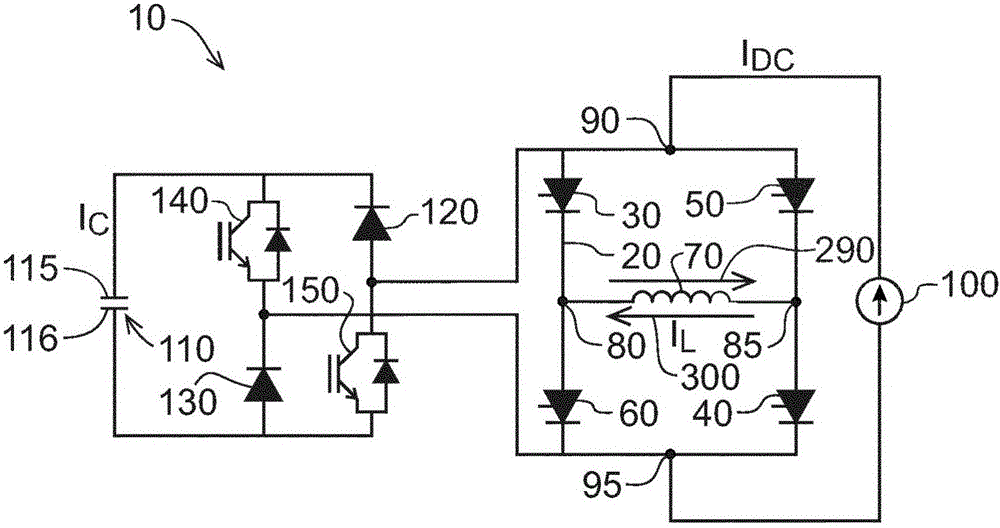
[0028] refer to figure 2 , in addition to the unit comprising four main switches 30, 40, 50, 60 in the form of thyristors, a commutation circuit 10 according to an embodiment of the present invention comprises an H-bridge via a first diode 120 and a second diode 130 20 voltage sources in the form of capacitors 110 connected in parallel. Capacitor 110 has a first terminal 115 and a sec...


PUM


Abstract

A commutation circuit (10) comprises a coil (70) connected to an H bridge (20), the H bridge (20) comprising four main switches (30, 40, 50, 60) for reversing polarity and a resulting coil current (IL) in the coil (70). The commutation circuit (10) further comprises a voltage source (110, 111) configured to generate a bypass current,and at least one auxiliary switch (140, 150, 160, 170, 180, 190, 210, 220, 230, 240, 250, 260, 270, 280) for controlling the bypass current to thereby decrease a switch current through at least one of the main switches (30, 40, 50, 60). By generating an appropriate bypass current with help of a voltage source (110, 111), a switch current through a desired main switch (30, 40, 50, 60) in a leading state can be decreased and eventually brought to zero. Zero current in its turn enables the use of thyristors as main switches (30, 40, 50, 60) as it results in the thyristors to be turned off automatically. Furthermore, decreased switch current at the switching moment reduces switching losses even in different types of switches such as GTOs and IGBTs.

Description

technical field [0001] The invention relates to a circuit for continuously reversing the direction of current flow in a coil. Background technique [0002] refer to figure 1 , the conventional commutation circuit 10 includes an H-bridge 20 with four main switches 30 , 40 , 50 , 60 . The coil 70 whose current direction is to be reversed is connected between the first output terminal 80 and the second output terminal 85 of the H-bridge 20 . The first input terminal 90 and the second input terminal 95 of the H-bridge 20 are connected to provide a constant cell current I DC The current source 100. The four main switches are properly operated so that the coil current I L Flow in the desired direction in the coil. For example, according to figure 1 , the first main switch 30 and the second main switch 40 are closed, and the coil current I L Flow is from left to right in the figure (positive direction 290). In order to reverse the coil current I L With flow from right to l...

Claims


Application Information

Patent Timeline
Patent Type & Authority Applications(China)
IPC IPC(8): H02P6/26H02P6/15
CPCH02P6/26H02P6/15
Inventor S·博斯加V-M·勒帕南M·帕斯马纳森R·钦柳玉敬
Owner ABB (SCHWEIZ) AG
Why Eureka
Try Eureka