High Efficiency Commutation Circuit
A commutation circuit and current-passing technology, which is applied in the direction of electronic commutator, single-phase motor control, etc.
- Summary
- Abstract
- Description
- Claims
- Application Information
AI Technical Summary
Problems solved by technology
Method used
Image
Examples
Embodiment Construction
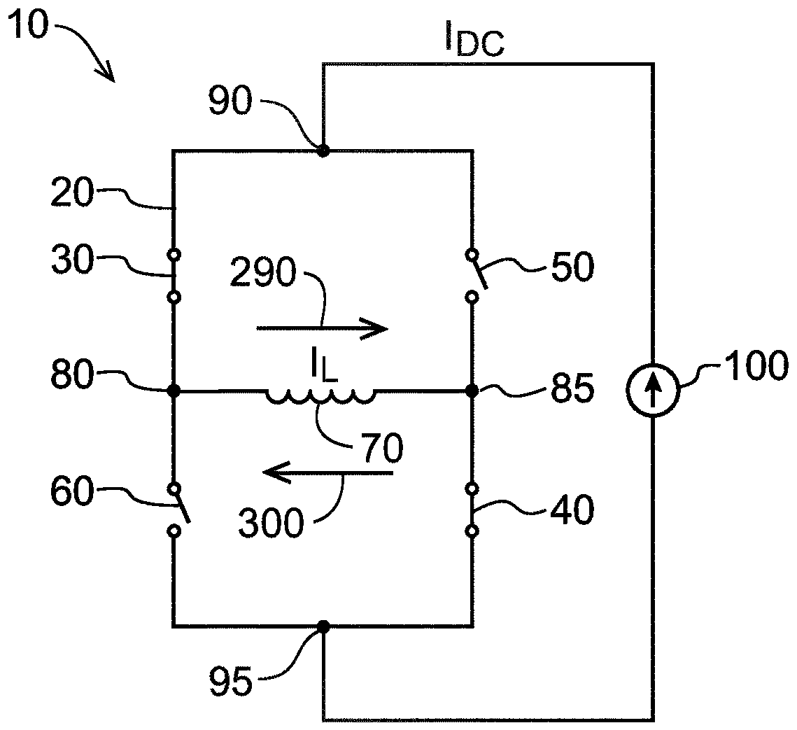
[0027] All embodiments of the invention disclosed herein include those corresponding to figure 1 In the subcircuits shown in , the only difference is that at least some of the main switches 30 , 40 , 50 , 60 according to the disclosed embodiments of the invention are implemented as thyristors. In the following description, an H-bridge 20 having four main switches 30, 40, 50, 60, a coil 70 connected to the output terminals 80, 85 of the H-bridge 20, and an input terminal 90, 95 connected to the H-bridge 20 are included. The subcircuits of the current source 100 will be referred to as "units"
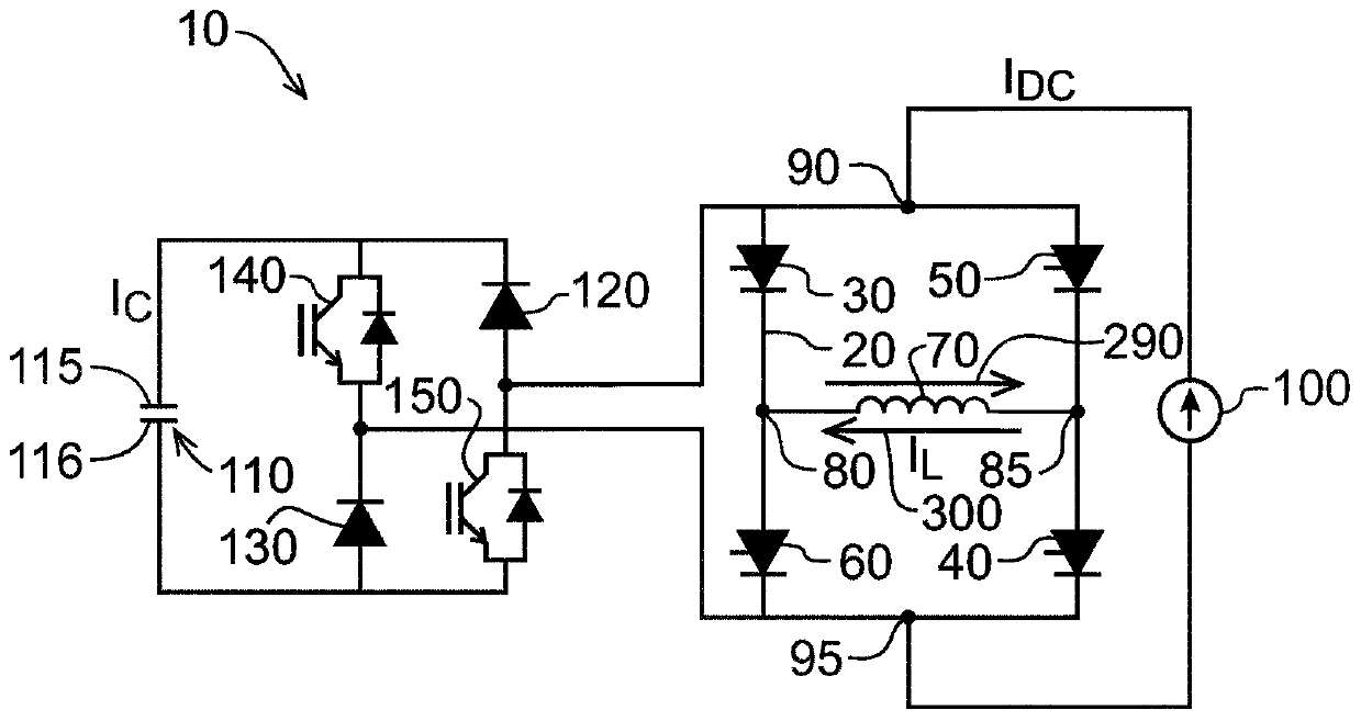
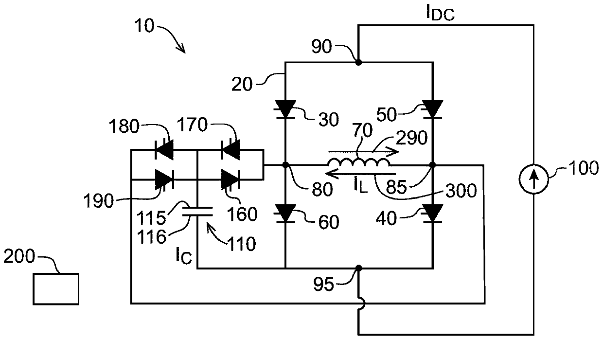
[0028] refer to figure 2 , in addition to the unit comprising four main switches 30, 40, 50, 60 in the form of thyristors, a commutation circuit 10 according to an embodiment of the present invention comprises an H-bridge via a first diode 120 and a second diode 130 20 voltage sources in the form of capacitors 110 connected in parallel. Capacitor 110 has a first terminal 115 and a sec...
PUM
 Abstract
Description
Claims
Application Information
 - R&D
- Intellectual Property
- Life Sciences
- Materials
- Tech Scout
- Unparalleled Data Quality
- Higher Quality Content
- 60% Fewer Hallucinations
Browse by: Latest US Patents, China's latest patents, Technical Efficacy Thesaurus, Application Domain, Technology Topic, Popular Technical Reports.
© 2025 PatSnap. All rights reserved.Legal|Privacy policy|Modern Slavery Act Transparency Statement|Sitemap|About US| Contact US: help@patsnap.com


