
Dispenser for packaging bag production line

A technology of production line and dispensing machine, which is applied to the device and coating of surface coating liquid, which can solve the problems of low efficiency, high cost, manual dispensing, etc.

Inactive Publication Date: 2016-11-23
江苏宇驰包装股份有限公司
View PDF0 Cites 2 Cited by
  • Summary
  • Abstract
  • Description
  • Claims
  • Application Information

AI Technical Summary

Problems solved by technology

[0002] With the development and progress of society, there are more and more demands for packaging bags in the market, and there are more and more requirements for the types of packaging bags. Most of the packaging bags are made of multi-layer paper materials. In the process of dispensing, it is necessary to carry out dispensing treatment between each layer of paper materials. Most of the existing dispensing treatment uses manual dispensing, which is inefficient.
With the popularization of automation, there have also been dispensing with manipulators, but the cost of dispensing with manipulators is relatively high.

Method used


Image

  • Dispenser for packaging bag production line
  • Dispenser for packaging bag production line

Examples


Embodiment 1

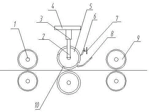
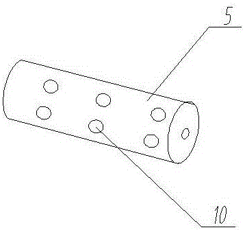
[0015] like figure 1 A dispensing machine for a packaging bag production line shown includes a frame 4 and a paper bag transmission mechanism, the frame 4 is arranged above the paper bag transmission mechanism, and the air cylinder 3 and the support 2 Connect the glue roller 5, the glue roller 5 is provided with a plurality of rubber grooves 10, a side of the glue roller 5 is provided with a rubber blocking plate 8, and the end of the glue blocking plate 8 is close to the The roller surface of the above-mentioned dispensing roller 5, and leave a gap of 3-5mm, the glue baffle 8 is used to place the glue, pour the glue on the glue baffle 8, and stick the glue on it when the dispensing roller 5 rotates , thereby realizing the gluing treatment of the dispensing roller 5 .

[0016] A scraper 6 is also arranged on one side of the glue dispensing roller 5 , and the scraper 6 is attached to the glue dispensing roller 5 . The scraper 6 is installed on the scraper mounting frame 7, an...

Embodiment 2

[0018] As a supplement of Embodiment 1 of the present invention, a cover body can be set on the glue tank 10 of the dispensing roller 5, and after the cover body is covered, the outer surface of the cover body is compatible with the roller surface of the dispensing roller 5, so that According to the needs of dispensing, select the glue tank 10 in some areas to use. For the unnecessary parts, you only need to cover the cover, which can adapt to the dispensing treatment of packaging bags of different specifications, without changing the dispensing roller, suitable for wide range.

[0019] A glue dispensing machine for a packaging bag production line provided by the present invention has a simple structure and is easy to operate. By setting a dispensing roller and a glue groove on the dispensing roller, the dispensing roller is glued through a glue blocking plate, and Use the scraper to scrape off the glue on the dispensing roller, and only keep the glue in the glue groove, so as...


PUM


Abstract

The invention discloses a dispensing machine for a packaging bag production line, which includes a frame and a paper bag transmission mechanism. The frame is arranged above the paper bag transmission mechanism, and a dispensing roller is connected to the frame through a cylinder and a bracket. , the dispensing roller is provided with a plurality of glue grooves, a rubber baffle is arranged on one side of the dispensing roller, the end of the glue baffle is close to the roller surface of the dispensing roller, and There is a gap of 3-5mm, and a scraper is also arranged on one side of the dispensing roller, and the scraper is attached to the dispensing roller. A glue dispensing machine for a packaging bag production line provided by the present invention has a simple structure and is easy to operate. By setting a dispensing roller and a glue groove on the dispensing roller, the dispensing roller is glued through a glue blocking plate, and Use the scraper to scrape off the glue on the dispensing roller, and only keep the glue in the glue groove, so as to achieve the purpose of dispensing.

Description

technical field [0001] The invention relates to the field of packaging materials, in particular to a glue dispenser for a packaging bag production line. Background technique [0002] With the development and progress of society, there are more and more demands for packaging bags in the market, and there are more and more requirements for the types of packaging bags. Most of the packaging bags are made of multi-layer paper materials. In the process of dispensing, it is necessary to carry out dispensing treatment between each layer of paper materials. Most of the existing dispensing treatment adopts manual dispensing, and its efficiency is low. With the popularization of the degree of automation, the use of manipulators for dispensing has also appeared, but the cost of manipulator dispensing is relatively high. Contents of the invention [0003] The object of the present invention is to provide a kind of dispensing machine for packaging bag production line in order to solve...

Claims


Application Information

Patent Timeline
IPC IPC(8): B05C1/12B05C1/08
CPCB05C1/12B05C1/0808B05C1/0817
Inventor 郝汉祝
Owner 江苏宇驰包装股份有限公司
Learn More