Hole punching structure of progressive die

A hole structure and mold technology, applied in the field of punching hole structure, can solve the problems of increasing the cost of the mold and the easy damage of the die edge of the die.

Inactive Publication Date: 2016-11-23
TIANJIN CHANGLE ELECTRONICS SCI & TECH
View PDF0 Cites 0 Cited by
  • Summary
  • Abstract
  • Description
  • Claims
  • Application Information

AI Technical Summary

Problems solved by technology

In traditional dies for punching holes and windows, the punch moves relatively horizontally. Due to the special structure of the pot frame, its side windows are larger and clo

Method used


Image

  • Hole punching structure of progressive die
  • Hole punching structure of progressive die

Examples


Embodiment Construction

[0013] The present invention will be further described in detail below in conjunction with the accompanying drawings and through specific embodiments.

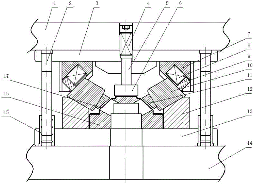
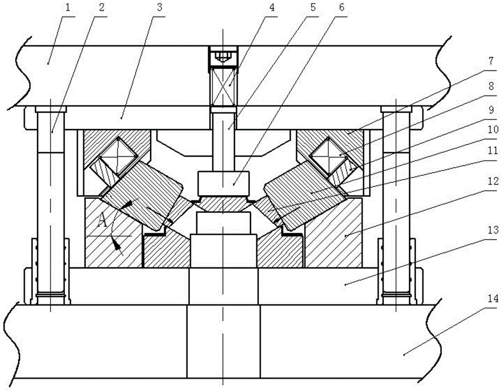
[0014] A punching hole structure of a progressive die, such as figure 1 Shown, comprise lower mold plate 14, lower mold fixed plate 13, die 16, punch assembly and upper template 1, lower mold fixed plate is installed on the described lower template, die is installed in the middle part of this lower mold fixed plate, and this die A workpiece 17 is installed on the top, and an upper template and an upper mold fixed plate 3 are arranged above the die, and the lower surfaces of the left and right sides of the upper template corresponding to the die are symmetrically installed downwards. The punch assembly is passed through the press ( (not shown in the figure) drives the upper template so as to drive the punch assembly to move downward to complete the purpose of punching the workpiece hole.

[0015] The innovation point of the pr...


PUM


Abstract

The invention relates to a hole punching structure of a progressive die. The hole punching structure of the progressive die comprises a lower die plate, a concave die, punch assemblies and an upper die plate. A lower die fixing plate is installed on the lower die plate. The concave die is installed in the middle of the lower die fixing plate. The upper die plate and an upper die fixing plate are arranged above the concave die. The punch assemblies are downwards arranged on the lower surfaces, corresponding to the concave die, of the left side and the right side of the upper die plate oppositely, obliquely and symmetrically. According to the hole punching structure, punches are arranged obliquely, so that a cutter edge of the concave die is arranged obliquely; and compared with a horizontal cutter edge, the oblique cutter edge can increase the wall thickness of the concave die under the situation of the identical concave die wall thickness, the strength is improved, and the concave die can bear higher punching force during punching. The hole punchingstructure of the progressive die is simple in structure and scientific and reasonable in design, punching is accurate, the concave die is not prone to being damaged, the maintenance time of the die is greatly shortened, and the maintenance cost of the die is greatly reduced.

Description

technical field [0001] The invention belongs to the field of dies, in particular to a punching hole structure of a progressive die. Background technique [0002] The loudspeaker is composed of multiple parts, and the basin frame is an essential part of the loudspeaker. The pot frame is made by stretch forming process. The main process of processing the pot frame is to stretch and form the sheet, and then go through the processes of shaping, trimming, bending, punching and flanging. [0003] Due to the limitations of the process, many holes, windows and flanges of the pot frame need to be punched and formed after stretching. In traditional dies for punching holes and windows, the punch moves relatively horizontally. Due to the special structure of the pot frame, the side windows are large and close to the end face, resulting in a thin wall of the punching die, which makes the die edge easily damaged. , Frequent replacement of the die increases the cost of the die. Conten...

Claims


Application Information

Patent Timeline
IPC IPC(8): B21D28/34
Inventor 崔志成芦家鹏
Owner TIANJIN CHANGLE ELECTRONICS SCI & TECH
Why Eureka
Try Eureka