Rubber roller

A technology of rubber rollers and roller cores, applied in printing, printing devices, etc., can solve the problems of temperature difference resistance, easy-to-pollute products and new cycle, fast aging, etc. performance effect

Inactive Publication Date: 2016-11-23
南京企航橡塑有限公司
View PDF9 Cites 2 Cited by
  • Summary
  • Abstract
  • Description
  • Claims
  • Application Information

AI Technical Summary

Problems solved by technology

[0003] The purpose of the present invention is to solve the problem of temperature difference between the two ends of the rubber surface of the existing rubber roller, and to provide a new type of rubber roller. The working area and the non-working area are made of different materials with high temperature resistance, so as to avoid the problems that the non-working area on both sides of the rubber roller ages faster than the working area, easily pollutes the product and has a short replacement cycle

Method used


Image

  • Rubber roller

Examples


Embodiment Construction

[0009] It is easy to understand that, according to the technical solution of the present invention, those skilled in the art can imagine various implementations of the rubber roller of the present invention without changing the essence and spirit of the present invention. Therefore, the following specific embodiments and drawings are only exemplary descriptions of the technical solution of the present invention, and should not be regarded as the entirety of the present invention or as a limitation or limitation on the technical solution of the present invention.

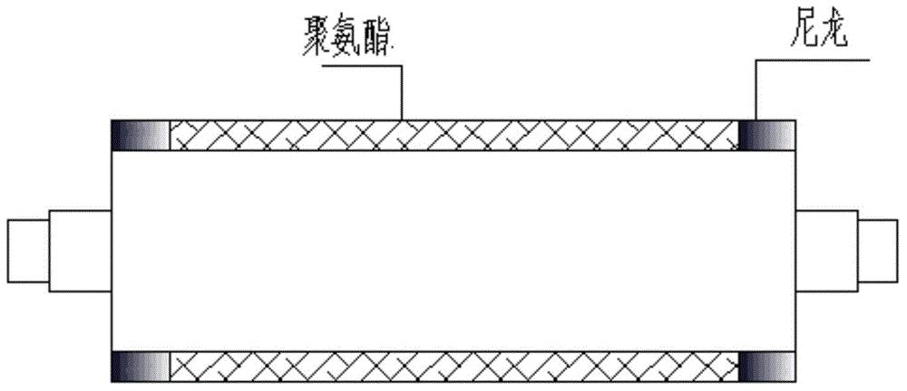
[0010] The rubber roller of the present invention is also covered with high-temperature-resistant materials on both sides of the polyurethane rubber layer on the surface of the roller core. The area where the polyurethane rubber layer is located is used as a working surface, which is in direct contact with the product to be processed during work, and the high-temperature-resistant material areas covered on both sides ...


PUM


Abstract

The invention provides a rubber roller. The rubber roller comprises a roller core. The surface of the roller core is covered with a polyurethane rubber layer. The parts, located on the two sides of the polyurethane rubber layer, of the surface of the roller core are further covered with high-temperature resisting materials. The high-temperature resisting materials are in seamless butt joint with the polyurethane rubber layer. The width of the polyurethane rubber layer is determined according to the work face width needed during using. The high-temperature resisting materials are nylon materials. The rubber layer wrapping the surface of the rubber roller is divided into a working area in the middle part and non-working areas at the two ends. Different high-temperature resisting materials are adopted in the working area and the non-working areas, and therefore the problems that non-working areas on the two sides of the rubber roller are faster than the working area in aging, products are prone to being polluted, and the updating period is short can be solved.

Description

technical field [0001] The invention belongs to the technical field of printing supplies, and in particular relates to a rubber roller. Background technique [0002] The rubber roller is a roller-shaped product made of metal or other materials as the core and covered with polyurethane material. According to the use, it can be divided into papermaking rubber rollers, printing and dyeing rubber rollers, printing rubber rollers, hulling rubber rollers, metallurgical rubber rollers and mimeograph rubber rollers. When polyurethane material is used to make rubber rollers, it is generally made by one-time casting. The roller core is positioned through the upper and lower flanges and fixed in the center of the cylindrical mold; the rubber liquid is poured into the mold cavity to fully cover the entire roller surface. The liquid rubber is solidified and shaped by heating; then the mold is released and processed to the required size of the finished product. When the rubber roller is...

Claims


Application Information

Patent Timeline
Patent Type & Authority Applications(China)
IPC IPC(8): B41J29/00
Inventor 王军
Owner 南京企航橡塑有限公司
Why Eureka
Try Eureka