Control method for vehicle speed limiting

A control method and technology for limiting vehicle speed, applied in the direction of speed/acceleration control, control device, control/regulation system, etc., can solve problems such as vehicle loss of control, and achieve the effect of stable and reliable operation and convenient installation.

Active Publication Date: 2016-11-23
NANJING UNIV OF SCI & TECH
View PDF9 Cites 7 Cited by
  • Summary
  • Abstract
  • Description
  • Claims
  • Application Information

AI Technical Summary

Problems solved by technology

Because these drivers are prone to nervousness during driving, especially in emergency situations, they often become overwhelmed, and it is very easy to step on the accelerator as a brake, resulting in serious consequences of loss of control of the vehicle.

Method used


Image

  • Control method for vehicle speed limiting
  • Control method for vehicle speed limiting
  • Control method for vehicle speed limiting

Examples


Embodiment 1

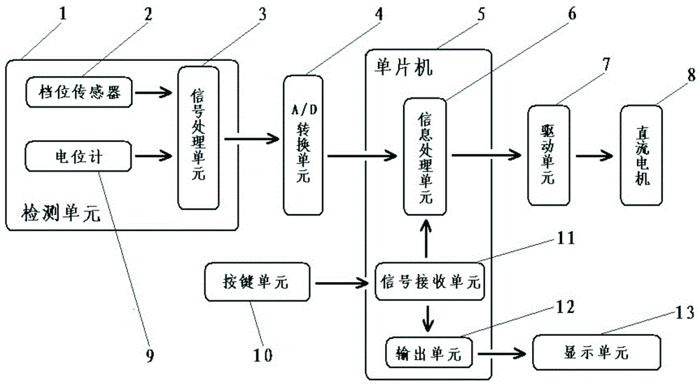
[0042] As shown in the accompanying drawings, a control system for limiting vehicle speed of this patent includes a single-chip microcomputer 5, an A / D conversion unit 4, a detection unit 1, a display unit 13, a key unit 10, a drive unit 7 and a limit device 15; the single-chip microcomputer 5 are respectively connected to the A / D conversion unit 4, the detection unit 1, the display unit 13, the key unit 10 and the drive unit 7, the A / D conversion unit 4 is also connected to the detection unit 1, and the drive unit 7 is also connected to the direct current of the limit device 15 Motor 8;

[0043]The detection unit 1 includes a gear sensor 2, a potentiometer 9 and a signal processing unit 3; the gear sensor 2 is used for real-time acquisition of the analog gear signal of the gear of the automobile, and the potentiometer 9 is used for real-time acquisition of the limit device 15 The analog stroke signal of the stroke where the electric push rod is located, the signal processing ...


PUM


Abstract

The invention discloses a control method for vehicle speed limiting. The maximum travel speed of an automobile can be set in advance, and the situation that the automobile is out of control due to sudden accelerator stepping performed by a driver can be avoided by shortening a stroke of an accelerator pedal.

Description

technical field [0001] The invention relates to the field of safe driving of automobiles, in particular to a control method for limiting vehicle speed. Background technique [0002] With the development of society, the use of cars has become more and more common. At the same time, frequent traffic accidents have also attracted people's attention. The survey found that most of the vehicles that are prone to traffic accidents are coach cars driven by driving school students and private cars driven by novices. Because these drivers are prone to nervousness during driving, especially in emergency situations, they often become overwhelmed, and it is very easy to step on the accelerator as a brake, resulting in serious consequences of loss of control of the vehicle. [0003] Aiming at this social problem, there is an urgent need for a vehicle speed limiting system, which can limit the maximum speed of the car while ensuring the free movement of the accelerator pedal within the s...

Claims


Application Information

Patent Timeline
Patent Type & Authority Applications(China)
IPC IPC(8): B60K31/00B60K26/02B60R16/023
CPCB60K26/02B60K31/00B60K31/02B60K2031/0091B60R16/023B60R16/0231B60W30/182
Inventor 闫冰倩
Owner NANJING UNIV OF SCI & TECH
Why Eureka
Try Eureka