Pile forming method of prefabricated cast-in-situ pile

A technology of cast-in-situ piles and prefabricated piles, which is applied in sheet pile walls, buildings, and foundation structure engineering. It can solve the problems of difficult pile sinking, long pile construction time, and high construction cost, and achieves a wide range of applicable strata and single pile bearing capacity High, the effect of improving the shear resistance

Active Publication Date: 2018-02-23
王庆伟
View PDF3 Cites 0 Cited by
  • Summary
  • Abstract
  • Description
  • Claims
  • Application Information

AI Technical Summary

Problems solved by technology

In addition, when the pile diameter of the immersed pile is large and the pile is long, it is not only difficult to sink the pipe, but also takes a long time to pour concrete on site, and it is very difficult to remove the outer pipe. Therefore, sometimes in order to increase the bearing capacity, the bottom end needs to be made. Enlarging the head makes it take a long time to build piles. Sometimes when there is a weak interlayer at the bottom of the expanding head, the length of the pile must be increased to pass through the weak interlayer. This also increases the limitation of the height of the pile machine tower, making it difficult to sink and pull the pipe. bigger
Prefabricated piles can be connected to piles due to the length of the pile, and the pile length is not limited by the height of the pile machine. However, the cost of solid prefabricated piles is high, and the shear strength of hollow prestressed pipe piles has the problem that it is difficult to meet the design requirements. Increasing the pile length When there is a hard interlayer in the ground, the construction noise will be large and the pile sinking will be difficult, and there will often be pile explosions, and sometimes lead holes will be required, resulting in high construction costs and slow construction speed.

Method used


Image

  • Pile forming method of prefabricated cast-in-situ pile
  • Pile forming method of prefabricated cast-in-situ pile
  • Pile forming method of prefabricated cast-in-situ pile

Examples


Embodiment Construction

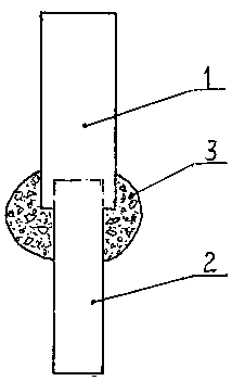
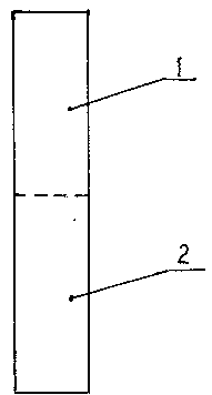
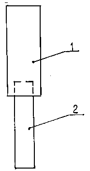
[0015] Examples, see attached figure 1 , 2 , the diameter of the upper cast-in-place pile 1 of the prefabricated cast-in-place pile is greater than the diameter of the lower precast pile 2, and the cast-in-place pile 1 wraps the top of the precast pile 2, and the connection between the precast pile 2 and the cast-in-place pile 1 is provided with or without concrete according to design requirements The filler 3 can also be a cement mixture filler, or the diameter of the upper cast-in-situ pile 1 and the lower prefabricated pile 2 is the same. The pile-forming method of prefabricated cast-in-place piles is as follows, refer to the attached image 3 , pile-forming method A: step Aa, move pile machine, align pile machine inner tube drilling tool 4 and outer tube drilling tool 5 to the pile position, adjust the positions of the front, back, left, and right sides of the drilling rig, so that the main rod of the drilling rig and the outer tube drilling tool 5 The front, rear, left,...


PUM


Abstract

The invention belongs to the field of construction, and particularly relates to a prefabricated cast-in-place pile and a pile-forming method thereof. The lower part of the pile is a prefabricated pile (2), and the upper part is a cast-in-place pile (1); wherein the diameter of the upper cast-in-place pile (1) is larger than that of the lower one The diameter of the prefabricated pile (2) and make the cast-in-place pile (1) wrap or not wrap the upper end of the precast pile (2), and the connection between the precast pile (2) and the cast-in-situ pile (1) is equipped with or without concrete according to the design requirements or cement mixture filler (3), or the diameter of the upper cast-in-place pile (1) is greater than the diameter of the lower prefabricated pile (2) as a butt joint form; the diameter of the upper cast-in-place pile (1) and the diameter of the lower prefabricated pile (2) The same; its pile-forming method is as follows: pile-forming method A and pile-forming method B, prefabricated cast-in-situ pile and its pile-forming method, the combination of prefabricated pile and cast-in-place pile is flexible, applicable to a wide range of strata, and the single pile has a high bearing capacity and has great advantages. Strong practicability, in line with the force mechanism of piles, saves the amount of concrete, greatly improves the construction speed and reduces the high cost.

Description

technical field [0001] The invention belongs to the field of construction, in particular to a method for forming prefabricated cast-in-place piles. Background technique [0002] At present, the pile length is limited by the height of the pile frame no matter whether it is foreign or domestic, the length of the pile cannot be too long. In addition, when the pile diameter of the immersed pile is large and the pile is long, it is not only difficult to sink the pipe, but also takes a long time to pour concrete on site, and it is very difficult to remove the outer pipe. Therefore, sometimes in order to increase the bearing capacity, the bottom end needs to be made. Enlarging the head makes it take a long time to build piles. Sometimes when there is a weak interlayer at the bottom of the expanding head, the length of the pile must be increased to pass through the weak interlayer. This also increases the limitation of the height of the pile machine tower, making it difficult to sin...

Claims


Application Information

Patent Timeline
Patent Type & Authority Patents(China)
IPC IPC(8): E02D5/50
Inventor 王庆伟林红艳王琢璐
Owner 王庆伟
Why Eureka
Try Eureka