Impact Rock Drilling Tools

An impact-type, drilling tool technology, applied in drilling equipment, earth-moving drilling, drill pipe, etc., can solve the problems of increasing the degree of local stress concentration, reducing the bearing arm, breaking the external thread, etc., and achieves resistance to axial load. Strong ability, good bending moment performance, good root strength

Active Publication Date: 2018-08-17
GUIYANG JIESHENG TECH IND DEV
View PDF7 Cites 1 Cited by
  • Summary
  • Abstract
  • Description
  • Claims
  • Application Information

AI Technical Summary

Problems solved by technology

[0004] 2) Since the stress is mostly concentrated at the end of the external thread of the drill rod, the drill rod is prone to breakage at the end of the external thread when subjected to a bending moment
In actual use, even if the fit relationship between the two inner tapered surfaces and the shaft shoulder is handled well (the interference degree of over-positioning is small), but when the structure is deformed under load (especially near the end surface of the inner thread), it is extremely It is possible that the right-angled end face of the drill rod shaft shoulder (or the corresponding internal thread end face) and the conical surface at the front end of the external thread section of the drill rod bear the bending moment, resulting in a sudden reduction in the bearing force arm and an increase in the local stress of the bending moment
At the same time, when the force on the shoulder surface (or the end surface of the internal thread) is uneven, the impact force transmitted (the main load transmitted by the combined component) will further increase the degree of local stress concentration, resulting in failure of the part in a short time
[0006] In addition, "CN10289110B" discloses a "drill bit for percussive rock drilling". This patent uses a section of internal thread to replace the relief groove in the threaded blind hole, although it can overcome the thinner trouser wall at the relief groove. defects, but the internal thread processing is more difficult
Not only that, due to the cancellation of the undercut, the internal thread extends all the way to the bottom of the threaded blind hole; therefore, a stress concentration will be formed between the end of the internal thread and the bottom of the threaded blind hole, resulting in the intersection of the internal thread and the bottom of the hole prone to cracks
In addition, since the drill rod of this patent is not equipped with a shaft shoulder, the end face of the trouser body and the thread occlusal line are similar to a simply supported beam structure, and the external thread will inevitably break at the thread occlusal line under the action of the bending moment, which is also the current traditional external thread. The main failure mode of thread

Method used


Image

  • Impact Rock Drilling Tools
  • Impact Rock Drilling Tools
  • Impact Rock Drilling Tools

Examples


Embodiment 1

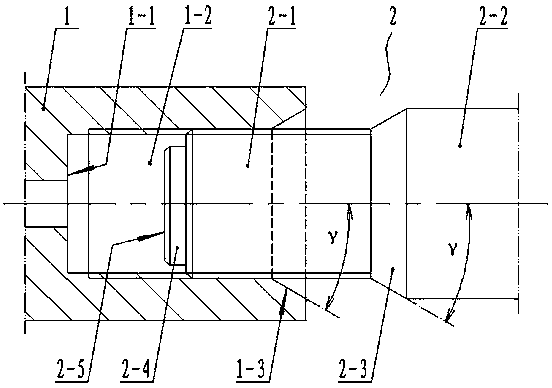
[0024] Such as Figure 1~3 As shown: the trouser body 1 of the drill bit is provided with a cylindrical threaded blind hole 1-2, and the drill rod 2 is connected with the threaded blind hole through an external threaded section 2-1 located at its front section. The drill rod 2 is a stepped shaft structure with a middle section 2-2, and the front end of the externally threaded section 2-1 of the drill rod 2 has a cylindrical transition section 2-4 with a diameter smaller than the threaded blind hole 1-2, and the length of the transition section is Less than or equal to the distance between the thread end of the threaded blind hole 1-2 and the hole bottom 1-1. In order to avoid stress concentration, the transition between the external thread section 2-1 and the middle section 2-2 is connected by a tapered shoulder 2-3; the included angle γ between the shaft shoulder 2-3 and the axis of the drill rod 2 is 1-10° , preferably 4°. In order to improve the bending strength at the en...

Embodiment 2

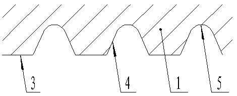
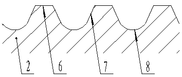
[0026] On the basis of the above-mentioned embodiments, the present invention can also adopt the following structure: In order to improve the strength of the threaded connection, the connecting thread of the drilling tool of the present invention is combined with a trapezoidal thread and a wave-like thread (the thread profile is in a wavy structure) compound thread. That is: the thread form of the threaded blind hole 1-2 is composed of a linear internal thread crest 3, a curved internal thread bottom 5, and one end is tangent to the internal thread bottom and the other end is connected to the internal thread crest 3 Correspondingly, the thread profile of the external thread section 2-1 is composed of a linear external thread bottom 6, a curved external thread crest 8, and one end connected to the external thread The top is tangent and the other end is connected with the external thread root 6 to form two sections of linear external thread flanks 7 . Wherein, the bottom 5 of t...


PUM


Abstract

The invention discloses an impact type rock drilling brazing tool and belongs to a rock drilling brazing tool. The invention aims at providing the rock drilling brazing tool with a long service life. The impact type rock drilling brazing tool comprises a tool body with a thread blind hole and a brazing rod which is matched and connected with the blind hole through an external thread arranged at a front-section part; the brazing rod (2) is of a ladder shaft structure; a cylindrical transition section (2-4) is arranged at the front end of an external thread section (2-1); the length of the transition section is smaller than or equal to the distance from the end part of the thread of the thread blind hole (1-2) to a hole bottom (1-1); the external thread section (2-1) and a middle section (2-2) are in transition connection through a tapered-surface shaft shoulder (2-3); an orifice of the thread blind hole (1-2) is provided with an inner tapered surface (1-3) adaptive to the shaft shoulder; when the external thread section (2-1) and the thread blind hole (1-2) are matched and tightened, a front end surface (2-5) of the transition section (2-4) is in contact with the hole bottom (1-1) of the thread blind hole (1-2). The tool body and the brazing rod of the brazing tool disclosed by the invention are not easy to break and an improved structure of the rock drilling brazing tool is provided.

Description

technical field [0001] The invention relates to a rock drilling tool, in particular to an impact type rock drilling tool. Background technique [0002] At present, the percussive rock drilling tool is usually formed by connecting the drill rod with the trouser body of the drill bit through threads. During the rock drilling process, the stress on the drill rod and the trouser body is relatively complicated and harsh, which may easily cause the drill tool to fail and affect the life of the drill tool. Through observation, it is found that there are two main types of failure of drilling tools: 1) fracture occurs at the end of the internal thread of the trouser body threaded blind hole; 2) fracture occurs at the end of the external thread section of the drill rod. After analysis, the main reasons for the breakage of trousers or drill rods are as follows: [0003] 1) Since there is a relief groove at the end of the internal thread, the wall of the trousers corresponding to the ...

Claims


Application Information

Patent Timeline
Patent Type & Authority Patents(China)
IPC IPC(8): E21B17/042
CPCE21B17/0426
Inventor 黄献萩武一苇
Owner GUIYANG JIESHENG TECH IND DEV
Why Eureka
Try Eureka