Eureka AIR delivers breakthrough ideas for toughest innovation challenges, trusted by R&D personnel around the world.

Gear and spindle transmission structure with clutch

A technology of main shaft drive and clutch gear, applied in the direction of gear transmission, belt/chain/gear, transmission, etc., can solve the problems such as the inability to provide power for the tool change gear pair and the absence of the main shaft box, achieving low cost and convenient production. , the effect of easy operation

Pending Publication Date: 2016-11-23
ANHUI CHIZHOU HOUSEHOLD MACHINE TOOL
View PDF0 Cites 0 Cited by
  • Summary
  • Abstract
  • Description
  • Claims
  • Application Information

AI Technical Summary

Problems solved by technology

[0002] The lathe headstock is also called the headstock. Its main task is to pass the rotational motion from the main motor through a series of speed change mechanisms so that the spindle can obtain the required different speeds of the forward and reverse directions. At the same time, the headstock splits part of the power. The motion is transmitted to the feed change gear pair, the traditional headstock and the feed change gear pair are powered at the same time, and there is no feed change gear pair in the traditional headstock, so the feed change gear pair cannot be controlled separately Provides power without spindle rotation

Method used


Image

  • Gear and spindle transmission structure with clutch

Examples


Embodiment 1

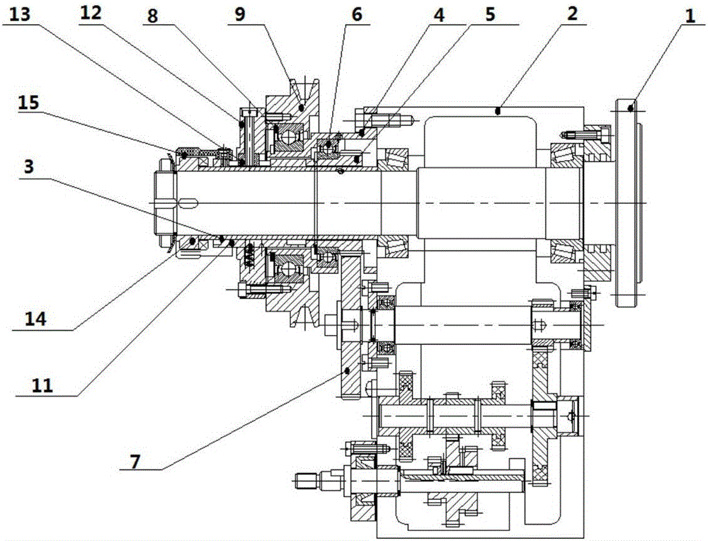
[0013] A gear and main shaft transmission structure with a clutch, such as figure 1 As shown, it includes the main shaft 1 and the box body 2, the left end of the main shaft 1 passes through the box body 2, the part of the main shaft 1 passing through the box body 2 is covered with a long spacer 3, and the bearing seat 4 is set on the long spacer 3 and the bottom of the bearing seat 4 is fixed on the left side of the box body 2 through a bolt structure, and the clutch gear 5 is fixed in the bearing seat 4 through the first bearing 6 and the retaining ring for the shaft. The input gear 7 on the box body 2 is meshed, and the bearing seat 4 at the connection between the clutch gear 5 and the input gear 7 is provided with an opening, and the first bearing 6 is fixed on the inner wall of the bearing seat 2 by tightening screws. , the second bearing 8 is set on the bearing seat 4 through the shaft retaining ring, the pulley 9 is set on the bearing seat 4 through the second bearing 8...


PUM


Abstract

The invention discloses a gear and spindle transmission structure with a clutch. The gear and spindle transmission structure comprises a spindle and a box. The left end of the spindle penetrates out of the box. The part, penetrating out of the box, of the spindle is sleeved with a long spacer bush. A bearing block is arranged on the long spacer bush in a sleeving manner, and the bottom of the bearing block is fixed to the left side of the box through a bolt structure. A clutch gear is fixed in the bearing block through a first bearing and a shaft check ring. The clutch gear is engaged with an input gear on the part, below the spindle, of the box. An opening is formed in the part, at the joint of the clutch gear and the input gear, of the bearing block. The first bearing is fixed to the inner wall of the bearing block through a fastening screw. A second bearing is arranged on the bearing block in a sleeving manner through a shaft check ring. A belt wheel is arranged on the bearing block in a sleeving manner through the second bearing. The gear and spindle transmission structure is novel in concept, simple in structure, convenient to manufacture, low in cost, easy and convenient to operate and good in effect; and the function that the gear and the spindle rotate asynchronously is effectively achieved through the clutch, energy is saved, and the enterprise cost is saved.

Description

technical field [0001] The invention relates to a gear and main shaft transmission structure with a clutch. Background technique [0002] The lathe headstock is also called the headstock. Its main task is to pass the rotational motion from the main motor through a series of speed change mechanisms so that the spindle can obtain the required different speeds of the forward and reverse directions. At the same time, the headstock splits part of the power. The motion is transmitted to the feed change gear pair, the traditional headstock and the feed change gear pair are powered at the same time, and there is no feed change gear pair in the traditional headstock, so the feed change gear pair cannot be controlled separately Power is supplied without the spindle turning. Contents of the invention [0003] Aiming at the problems existing in the prior art, the object of the present invention is to design and provide a gear and main shaft transmission structure with a clutch, which...

Claims


Application Information

Patent Timeline
IPC IPC(8): F16H3/093
CPCF16H3/093
Inventor 陈关元
Owner ANHUI CHIZHOU HOUSEHOLD MACHINE TOOL
Why Eureka
Eureka Blog
Learn More