Electric hot melt salt valve

A technology of electric heating and valves, applied in the direction of valve details, valve devices, valve heating/cooling devices, etc., to achieve smooth cut-off, save manpower and time costs, and avoid losses

Inactive Publication Date: 2016-11-23
天津滨海光热发电投资有限公司
View PDF0 Cites 4 Cited by
  • Summary
  • Abstract
  • Description
  • Claims
  • Application Information

AI Technical Summary

Problems solved by technology

The power of the electric heating cable is mainly controlled by the heat transfer process, and the output power is automatically adjusted according to the temperature of the heated system, while the traditional constant power heater does not have this function

Method used


Image

  • Electric hot melt salt valve
  • Electric hot melt salt valve

Examples


Embodiment Construction

[0018] The technical solutions of the present invention will be further described below through specific examples.

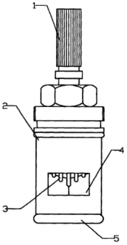
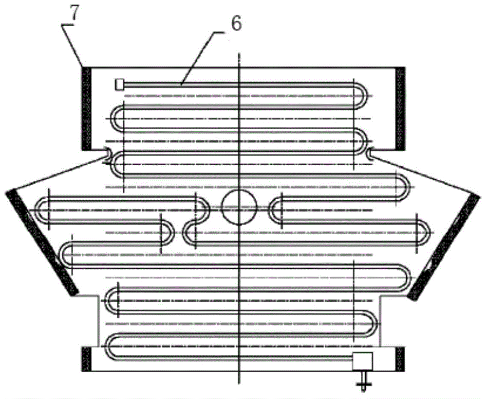
[0019] Such as figure 1 with figure 2 As shown, wherein, 1 is a valve stem, 2 is a valve seat, 3 is a columnar body, 4 is a liquid port, 5 is a seal, 6 is an electric heating wire, and 7 is a Velcro.

[0020] Electric molten salt valve, including valve, electric heating cable and power junction box, the valve includes a cylindrical valve seat, a valve stem set in the cylindrical valve seat, a liquid port is arranged on the valve seat, and the inside of the valve stem is inserted into the valve In the seat, a movable valve disc is arranged on the inner side of the valve stem, and an upper gap is provided on the lower surface of the movable valve disc, and a fixed valve disc corresponding to the circumferential direction of the valve seat is arranged on the inner side of the valve seat and the lower side of the movable valve disc. There is a lower gap on the up...


PUM


Abstract

The invention provides an electric hot melt salt valve. The valve comprises a cylindrical valve seat and a valve rod arranged in the cylindrical valve seat, wherein a liquid passing port is formed in the valve seat; the inner side of the valve rod is inserted into the valve seat; a movable valve clack is arranged at the inner side of the valve rod; an upper gap is formed in the lower surface of the movable valve clack; fixed valve clacks corresponding to the circumferential direction of the valve seat are arranged at the inner side of the valve seat and the lower side of the movable valve clack; a lower gap is formed in the upper surface of each fixed valve clack; the positions of the upper gap and the lower gaps correspond to the position of the liquid passing port; a silencer is arranged at the upper gap of the movable valve clack and adopts an elastic structure; an electric tracing band adopts a flexible wrapping substance which can be wound on the valve; electric heating wires are arranged on an insulating layer; nylon adherent buckles which are used for being mutually buckled are correspondingly arranged on an inner waterproof layer and an outer rainproof layer; and a power junction box is connected with the electric heating wires through leads. The valve is arranged at one time, and mounting and construction of an electric heating device are avoided, so that great labor force and time cost are reduced.

Description

technical field [0001] The invention relates to the technical field of valve control, in particular to an electric heating molten salt valve. Background technique [0002] A valve is a device used to control the direction, pressure, and flow of a fluid in a fluid system. It is a device that allows the medium (liquid, gas, powder) in the piping and equipment to flow or stop and can control its flow. [0003] The valve is a control component in the pipeline fluid delivery system. It is used to change the passage section and the flow direction of the medium, and has the functions of diversion, cut-off, throttling, check, diversion or overflow relief. Valves used for fluid control range from the simplest shut-off valve to various valves used in extremely complex automatic control systems. Valves for industrial pipelines. It can be used to control the flow of various types of fluids such as water, steam, oil, gas, mud, various corrosive media, liquid metals and radioactive flui...

Claims


Application Information

Patent Timeline
Patent Type & Authority Applications(China)
IPC IPC(8): F16K49/00
CPCF16K49/002
Inventor 官景栋
Owner 天津滨海光热发电投资有限公司
Why Eureka
Try Eureka