A disposable liquid collection device

A one-time, liquid collection technology, applied in the field of medical devices, can solve problems such as affecting the health of medical staff or family members, getting urine or clothes, environmental pollution, etc., and is suitable for large-scale industrial production applications, avoiding urine odor Diffusion, wide-ranging effects

Active Publication Date: 2017-09-19
CHEOBE DONGGUAN PACKAGE CO LTD
View PDF1 Cites 0 Cited by
  • Summary
  • Abstract
  • Description
  • Claims
  • Application Information

AI Technical Summary

Problems solved by technology

[0003] There are many defects in the above-mentioned method of collecting urine samples. For example, it is difficult for some testees to discharge urine into the urine cup, and it is easy to get urine on hands or clothes. This collection method is unhygienic; If you have a serious infectious disease and your body is inconvenient to move, you need medical staff or family members to help you collect urine. If the urine sample is splashed or leaked during the sampling process, it is easy for the medical staff or family members to suffer from infectious diseases and affect the medical care. The health of personnel or family members has brought a lot of trouble; and the collected urine samples are placed open, during the detection process, the pungent odor of the urine samples will cause serious pollution to the environment, affecting the working environment and work efficiency of medical staff, and the installation Paper cups for good urine take up a lot of space, and a large space needs to be reserved for storing urine samples to be tested, which wastes resources
[0004] Therefore, some leak-proof devices that are specially used to collect urine have gradually appeared on the market, such as Chinese patent CN203916684U, which is called a self-closing leak-proof quantitative liquid collection device, a self-closing leak-proof quantitative liquid collection device , including a liquid storage tube, a leak-proof part and a liquid-taking part; the liquid storage tube includes an opening and a liquid storage chamber; the leak-proof part is provided with at least one axial through hole; the leak-proof part is located at the The opening part; the liquid-taking part includes a liquid-guiding channel and an exhaust channel; the liquid-taking part cooperates with the leak-proof part, on the one hand to prevent leakage through the leak-proof part, and on the other hand to solve the problem through the exhaust channel. The technical problems of clogging and unsmooth drainage are easy to occur during drainage
[0005] The structure of the above-mentioned device has the following problems. When the amount of liquid taken is large or the waiting time is long, it is necessary to use a blocking body to block the liquid storage pipe. The blocking body is generally a separate component and is located at the bottom of the liquid storage pipe. Therefore, it is necessary to There are at least three steps to complete the liquid extraction process. First, collect the liquid; then separate the liquid extraction part, and finally use the blocking body to block the liquid storage tube. When removing the blocking body, if the force is too large, the urine may leak Or if it is spilled, if the force is too small, it may not be removed, and it will increase the number of components and increase the production cost; in addition, for male users, after the liquid collection step is completed, the liquid collection device is usually placed on the sidelines, Then put on the underwear first, then separate the liquid-taking parts, and finally block the liquid-taking tube. When the liquid-taking device is placed obliquely, the urine in the liquid-taking tube may leak out from the back; since the liquid-taking device is a disposable product, its The quantity used is very large, how to simplify the structure, simplify the operation steps, improve user experience, reduce costs, and achieve the same technical effect at the same time is an urgent problem to be solved

Method used


Image

  • A disposable liquid collection device
  • A disposable liquid collection device
  • A disposable liquid collection device

Examples


Embodiment 1

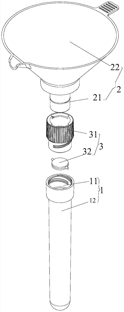
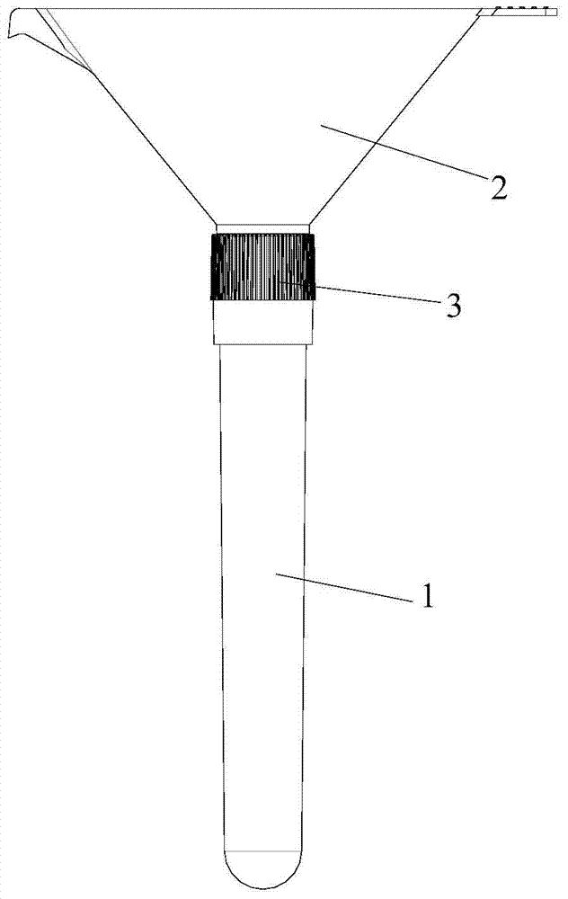
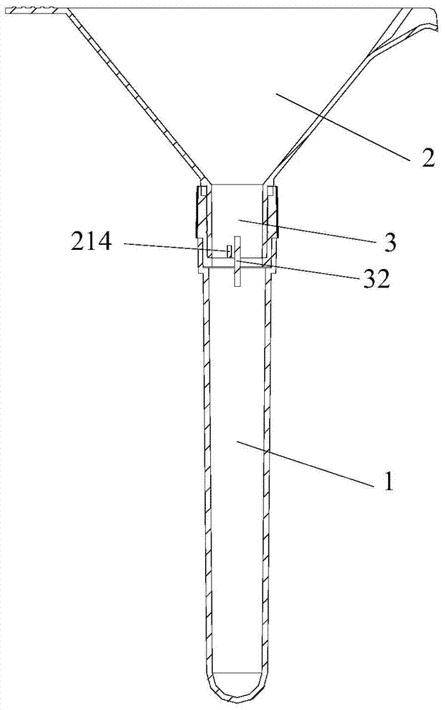
[0049] as attached Figure 1-22 As shown, a disposable liquid collection device includes a liquid storage tube 1 and a liquid guide device 2, the liquid storage tube 1 includes an opening 11 and a liquid storage cavity 12, and the liquid guide device 2 is provided with a guide A liquid channel 21 and an annular side wall 22, one end of the liquid guiding channel 21 is a liquid inlet 211, and the other end is a liquid outlet 212, and a one-way valve 3 is included, and the one-way valve 3 includes a hollow valve cover 31 And the valve 32 pivotally connected to the inner wall of the valve cover 31, the inner wall of the liquid guiding channel 21 is fixed with a push plate 214, and the liquid guiding device 2 is detachably mounted on the upper part 311 of the valve cover 31, so The liquid storage pipe 1 is detachably mounted on the lower part 312 of the valve cover 31, the push plate 214 partially or completely overlaps with the valve 32, and when the liquid guiding device 2 is ro...


PUM

PropertyMeasurementUnit
diameteraaaaaaaaaa
heightaaaaaaaaaa
diameteraaaaaaaaaa

Abstract

The present invention relates to the technical field of medical devices, in particular to a disposable liquid collection device, which includes a liquid storage tube and a liquid guiding device, the liquid storage tube includes an opening and a liquid storage cavity, and the liquid guiding device is provided with a liquid guiding channel and a liquid guiding device. An annular side wall, one end of the liquid guiding channel is a liquid inlet, the other end is a liquid outlet, and a one-way valve is also included. The one-way valve includes a hollow valve cover and a valve pivotally connected to the inner wall of the valve cover. The inner wall is fixed with a push plate, the liquid diversion device is detachably installed on the upper part of the valve cover, and the liquid storage pipe is detachably installed on the lower part of the valve cover, the push plate overlaps with the valve partially or completely, and the rotating liquid guides device, the push plate pushes the valve down to close the valve cover. Compared with the prior art, the disposable liquid collection device of the present invention collects the urine in the liquid storage tube, and the one-way valve on the liquid storage tube prevents the urine from leaking. Leakage and backflow, simplified structure, cost saving, simple and hygienic operation, and convenient for patients to use.

Description

technical field [0001] The invention relates to the technical field of medical instruments, in particular to a disposable liquid collection device. Background technique [0002] The results of urinalysis provide information for the diagnosis of many diseases and for judging the current health status of the subjects. Therefore, various hospitals and test centers routinely perform urine tests on a large number of patients. Under normal circumstances, the subject needs to go to the bathroom to collect a urine sample in a paper cup, and then put the paper cup on the designated shelf in the test room or pour the urine into a designated test tube, and then send it to the laboratory for urine analysis. [0003] There are many defects in the above-mentioned method of collecting urine samples. For example, it is difficult for some testees to discharge urine into the urine cup, and it is easy to get urine on hands or clothes. This collection method is unhygienic; If you have a seriou...

Claims


Application Information

Patent Timeline
Patent Type & Authority Patents(China)
IPC IPC(8): G01N1/20
Inventor 周荣励
Owner CHEOBE DONGGUAN PACKAGE CO LTD
Why Eureka
Try Eureka