High-temperature resistant composite derivation-rectifying roller expansion joint

A compound type, rectifying roller technology, which is applied to expansion compensation devices for pipelines, thermal insulation, pipes/pipe joints/fittings, etc., can solve the problem of short service life, poor thermal insulation performance, heat-resistant temperature Low problems, to achieve the effect of improving thermal insulation performance, good low temperature and high temperature strength, and reducing emission

Inactive Publication Date: 2016-11-23
江苏苏创管业科技有限公司
View PDF8 Cites 1 Cited by
  • Summary
  • Abstract
  • Description
  • Claims
  • Application Information

AI Technical Summary

Problems solved by technology

The furnace roller expansion joints used in the more advanced furnace rolls use non-metallic rectifying roller expansion joints. The existing rectifying roller expansion joints include drum skins and flanges. The drum skins are multi-layer composite structures, including inner to outer The steel wire mesh, high silica ceramic fiber cloth layer, and glass fiber cloth that are glued to each other in sequence, the correction roller expansion joint with this structure can meet the radial and axial compensation requirements required for the use of the correction roller, but the heat insulation performance is not good. Well, the heat-resistant temperature is low, and a lot of heat is emitted from the drum skin. On the one hand, the service life of the guide roller expansion joint is short, and on the other hand, it also causes a lot of energy loss

Method used


Image

  • High-temperature resistant composite derivation-rectifying roller expansion joint
  • High-temperature resistant composite derivation-rectifying roller expansion joint

Examples


Embodiment Construction

[0016] Hereinafter, the present invention will be further explained based on the drawings and the embodiments.

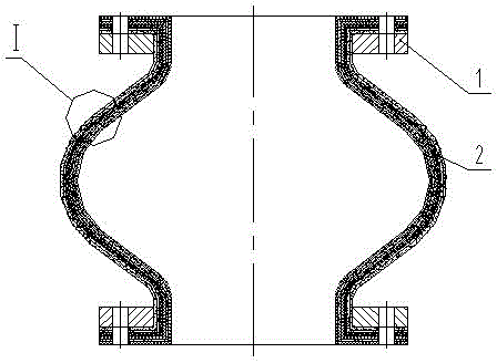
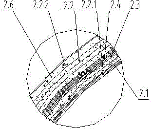
[0017] The high temperature resistant composite correction roller expansion joint shown in the figure includes a drum-shaped skin 2 and a flange 1. The flange 1 is fixedly connected to both ends of the drum-shaped skin 2; the drum-shaped skin 2 is a multilayer composite structure, including The steel mesh I2.1, the high silica ceramic fiber cloth layer 2.2, and the glass fiber cloth 2.6 which are adhered to each other sequentially from the inside to the outside; the high silica ceramic fiber cloth layer 2.2 is composed of multiple layers of high silica ceramic fiber cloth. Including the high silica ceramic fiber cloth layer I 2.2.1 on the outside of the steel mesh Ⅰ2.1, the high silica ceramic fiber cloth layer II 2.2.2 on the inner side of the glass fiber cloth 2.6; the high silica ceramic fiber cloth layer I 2.2.1, the high silica fiber cloth layer The ceramic fiber ...


PUM


Abstract

The present invention discloses a high-temperature resistant composite derivation-rectifying roller expansion joint, comprising a drum-shaped skin, and flanges fixedly connected to two ends of the drum-shaped skin. The drum-shaped skin is of a multi-layer composite structure, and comprises a steel wire mesh I, a high silica ceramic fiber cloth layer and a glass fiber cloth that are pasted to one another in sequence from inside to outside. The high silica ceramic fiber cloth layer is composited of a plurality of layers of high silica ceramic fiber cloth, including a high silica ceramic fiber cloth layer I outside the steel wire mesh I, and a high silica ceramic fiber cloth layer II inside the glass fiber cloth; an aerogel thermal insulating layer is disposed between the high silica ceramic fiber cloth layer I and the high silica ceramic fiber cloth layer II. A further improvement is made on that a steel wire mesh II is disposed inside or outside the aerogel thermal insulating layer. The high-temperature resistant composite derivation-rectifying roller expansion joint is characterized in that organic silicone is integrally vulcanized such that the outer wall of the glass fiber cloth and the inner wall of the steel wire mesh I are covered with vulcanized layers. The high-temperature resistant composite derivation-rectifying roller expansion joint is good in thermal insulation property, resistant to high temperatures, high in structural strength, good in toughness, very long in service life, and low in energy loss.

Description

Technical field [0001] The invention relates to a pipeline compensation device, in particular to a non-metallic expansion joint for annealing furnaces in the iron and steel industry. Background technique [0002] Furnace roll expansion joints are mainly used in annealing furnaces in the iron and steel industry, and are important components to ensure the stability of the roll system in the furnace and the entire unit. The furnace roll expansion joints used by the more advanced furnace rolls use non-metallic correction roll expansion joints. The existing correction roll expansion joints include drum skins and flanges. The drum skins are multi-layer composite structures, including from the inside to the outside. The steel wire mesh, the high silica ceramic fiber cloth layer, and the glass fiber cloth are successively bonded to each other. The expansion joint of the correction roller with this structure can meet the requirements of radial and axial compensation required by the use of...

Claims


Application Information

Patent Timeline
Patent Type & Authority Applications(China)
IPC IPC(8): F16L51/00F16L59/02F16L58/00
CPCF16L51/00F16L58/00F16L59/029
Inventor 卢勇
Owner 江苏苏创管业科技有限公司
Why Eureka
Try Eureka