Test tube recognition method and test tube recognition device for detection equipment

A technology of detection equipment and identification method, applied in the field of medical devices, can solve the problems of increasing operation steps, wasting operation time, sampling failure, etc., and achieve the effect of saving operation time, simplifying operation steps, and reducing the risk of misoperation

Inactive Publication Date: 2016-11-23
SHANGHAI UPPER BIO TECH PHARMA
View PDF4 Cites 5 Cited by
  • Summary
  • Abstract
  • Description
  • Claims
  • Application Information

AI Technical Summary

Problems solved by technology

In actual operation of these test tubes, if the same item is tested, the same detection device will be used. However, one detection device can only perform batch detection on the same type of test tubes. If there are several different types of test tubes to be tested, only Can be put into the detection device one by one for detection, which leads to increased operation steps, waste of operation time and increased risk of misoperation
[0003] For example: Chinese patent application "a POCT tester with automatic sampling device", the application number is 201210254313.0, the tester can automatically inject samples, but the same batch can only automatically inject samples of the same test tube, if in the same Different types of test tubes are placed in the batch, because they cannot be automatically identified, which will lead to sampling failure

Method used


Image

  • Test tube recognition method and test tube recognition device for detection equipment

Examples


Embodiment Construction

[0014] The present invention will be further described below in conjunction with specific embodiments and accompanying drawings.

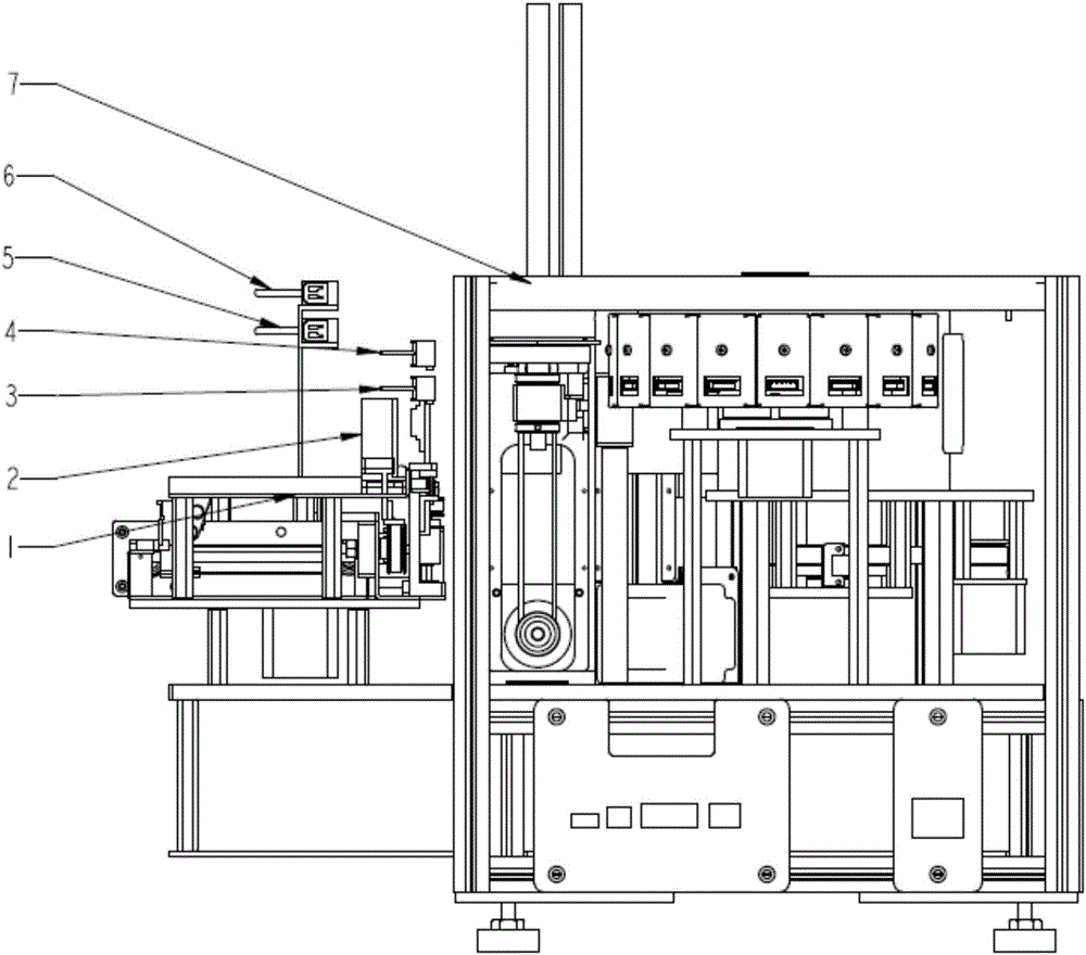
[0015] A method for identifying test tubes of detection equipment. A row of photoelectric rocker switches is installed above the automatic sample feeding device of the detection equipment, and a row of reflective sensors is installed above the row of photoelectric rocker switches; when installed, each photoelectric rocker switch corresponds to The height of a test tube; using the different heights of various test tubes can trigger different numbers of photoelectric rocker switches to identify different types of test tubes, and at the same time identify the capped state and uncapped state of the test tube through the reflected signal received by the reflective sensor .

[0016] Wherein, the reflective sensor specifically selects a slow reflective sensor.

[0017] Such as figure 1 As shown, it is a small POCT tester equipped with the test tube iden...


PUM


Abstract

The invention relates to a test tube recognition method for detection equipment and belongs to the field of medical instrument and appliances. The test tube recognition method for the detection equipment is characterized in that a line of photoelectric rocker type switches are arranged above an automatic sampling device of the detection equipment; various test tubes trigger the photoelectric rocker type switches of different quantities so as to recognize the test tubes of different kinds; meanwhile, a capping state and an uncapping state of the test tubes are recognized by a reflection signal received by a reflective sensor. By using the method, when different test tubes are used for detecting the same program, batch sampling on one detection device can be realized, so that operation steps are simplified, and operation time is saved.

Description

technical field [0001] The invention relates to the field of medical devices, in particular to a method for identifying a test tube of a testing device and an identifying device thereof. Background technique [0002] During the use of medical devices, due to different regions and differences in the usage habits of operators, various sampling test tubes will be encountered, such as those with different structural shapes and different sample volumes. In actual operation of these test tubes, if the same item is tested, the same detection device will be used. However, one detection device can only perform batch detection on the same type of test tubes. If there are several different types of test tubes to be tested, only It can be put into the detection device one by one for detection, which leads to increased operation steps, waste of operation time and increased risk of misoperation. [0003] For example: Chinese patent application "a POCT tester with automatic sampling devic...

Claims


Application Information

Patent Timeline
Patent Type & Authority Applications(China)
IPC IPC(8): G01N35/10
CPCG01N35/10
Inventor 黄剑峰易奇浩周深杨宏徐国祥李福刚徐建新
Owner SHANGHAI UPPER BIO TECH PHARMA
Why Eureka
Try Eureka