

Display equipment
A display device and display panel technology, applied in mechanical equipment, light guides, optics, etc., can solve problems such as time-consuming and increased manufacturing costs
- Summary
- Abstract
- Description
- Claims
- Application Information
AI Technical Summary
Problems solved by technology
Method used
Image

Examples
Embodiment 1
[0040] Embodiment 1: the preparation method of light guide plate
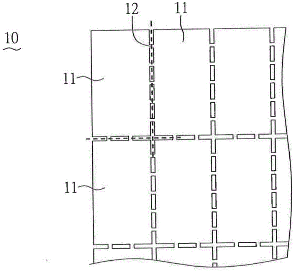
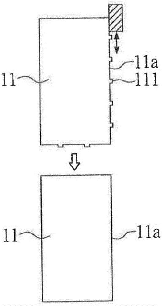
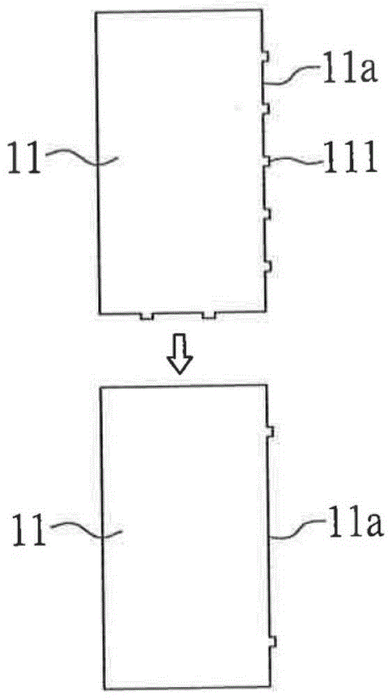
[0041] see Figure 1A A light guide plate mother board 10 is formed by hot pressing or injection, the light guide plate mother board 10 includes a plurality of light guide unit boards 11, and there are more than one connecting piece between adjacent light guide unit boards 11 12 to connect the light guide unit boards 11 to each other. Therefore, during the manufacturing process, the two adjacent light guide unit boards 11 can be disconnected by bending the connecting pieces 12 . The disconnected connector 12 remains on the edge of the light guide unit plate 11 to form a protrusion 111. At this time, a polishing step can be selected to remove the surrounding protrusion 111 (such as Figure 1B ); or the edges of these light guide unit plates 11 may not be polished or partially polished, so as to completely (not shown) or partially retain these protrusions 111 (such as Figure 1C ), in this case, the protruding...
Embodiment 2
[0043] Example 2: Connector and light guide plate
[0044] Such as Figure 2A shown as Figure 1A A light guide plate motherboard 10 including a plurality of light guide unit plates 11, and the adjacent light guide unit plates 11 are connected to each other by at least one connecting piece 12, Figure 2B for Figure 2A The A-A profile, while Figure 2C then Figure 2A The B-B profile. Figure 2A Among them, L1 represents the width of a single light guide unit plate 11; L2 represents the length of a single light guide unit plate 11; L1_bre represents the length of a connector 12; and L2_bre represents the width of a connector 12, in this embodiment, its Satisfy the relationship of L1>L1_bre and L2>L2_bre. In addition, the thickness T_bre of the connector 12 is smaller than the thickness T of the light guide plate motherboard 10, such as Figure 2A and 2B As shown, that is, when at least two adjacent light guide unit boards 11 are disconnected along the connecting member...
Embodiment 3
[0060] Example 3: bendable light guide plate
[0061] Another aspect of the present invention also provides a display device, wherein the used light guide plate 1 includes a plurality of light guide unit plates 11, and there are more than one connecting piece between adjacent light guide unit plates 11 12 to connect the light guide unit boards 11 to each other. Wherein, the length and width of the connecting member 12 are the same as those in Embodiment 2, so details will not be repeated here.
[0062] When the plurality of light guide unit plates 11 are bent so that the connectors 12 are bent without breaking, the obtained light guide plate can be applied in curved displays, such as Figure 10A and Figure 10B As shown, at least one convex portion 111 with a rough area is formed on the light incident surface 11a (such as Figure 10A ), or only exhibit rough regions 112 without protrusions (such as Figure 10B )Case. The number of light guide unit plates 11 constituting t...
PUM
| Property | Measurement | Unit |
|---|---|---|
| surface roughness | aaaaa | aaaaa |
| surface roughness | aaaaa | aaaaa |
| thickness | aaaaa | aaaaa |
Abstract
Description
Claims
Application Information