Fiber welding method and fusion splicer

An optical fiber fusion splicer and optical fiber fusion splicing technology, applied in the field of optical communication, can solve the problems of large connection loss, high machine cost, affecting signal transmission, etc., and achieve the effect of ensuring fusion splicing accuracy, realizing miniaturization, and reducing costs.

Inactive Publication Date: 2016-11-23
INNO INSTR (CHINA) INC
View PDF0 Cites 11 Cited by
  • Summary
  • Abstract
  • Description
  • Claims
  • Application Information

AI Technical Summary

Problems solved by technology

[0004] The mechanical fixed fusion splicing optical fiber fusion splicer only aligns the cladding of the optical fiber through the lens, and completes the fusion splicing of the optical fiber through the motor. It is generally used for FTTH (Fiber To The Home) construction, and it cannot perform optical fiber V The precise alignment of the slots cannot ensure that the optical fibers at the left and right ends are completely aligned, resulting in a large splice loss, usually greater than 0.1Db, which affects signal transmission
[0005] The precision-adjustable fiber optic fusion splicer is equipped with a specially designed optical lens. Through the lens focusing, the position of the fiber core is accurately measured, and then the precision six-motor core alignment mechanism and software algorithm are used to perform fiber core adjustment and precise alignment, so that it can Accurately identify the fiber type and automatically select the matching splicing mode to ensure the splicing quality. It has high technical content and is generally used for trunk line construction. Adapt to the development requirements of machine miniaturization in the industry, and the cost of the machine is too high

Method used

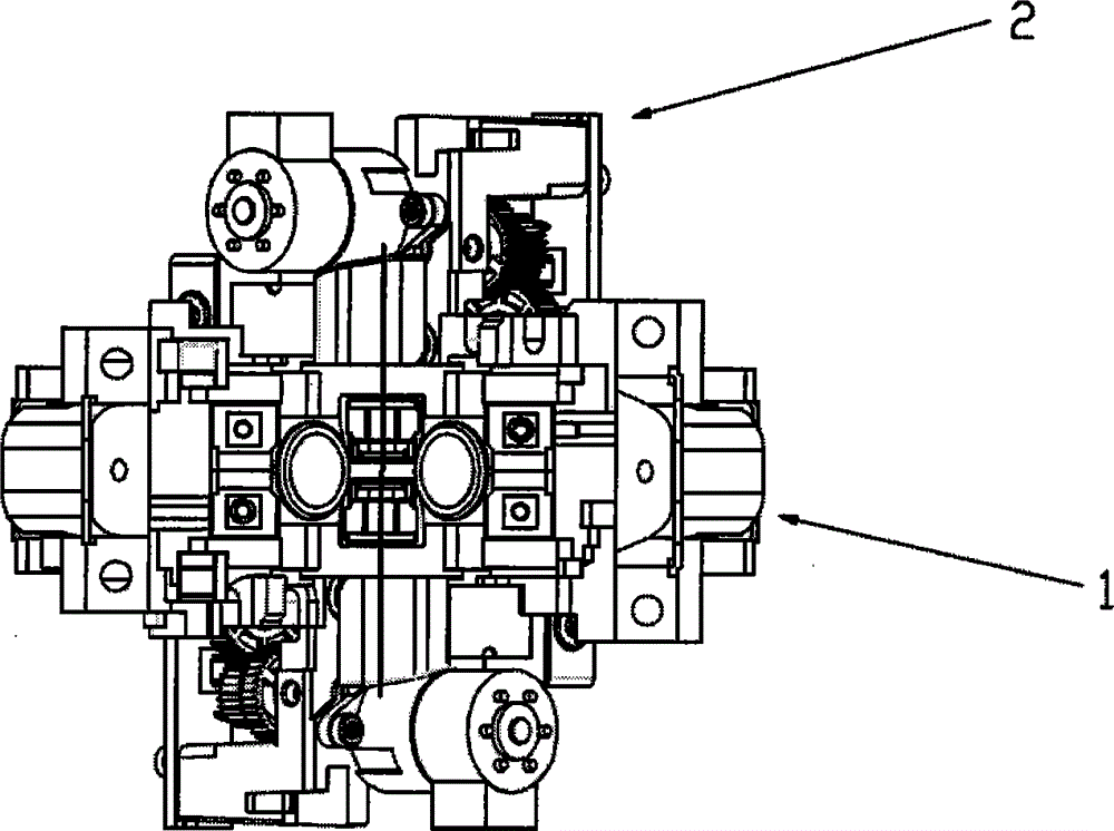
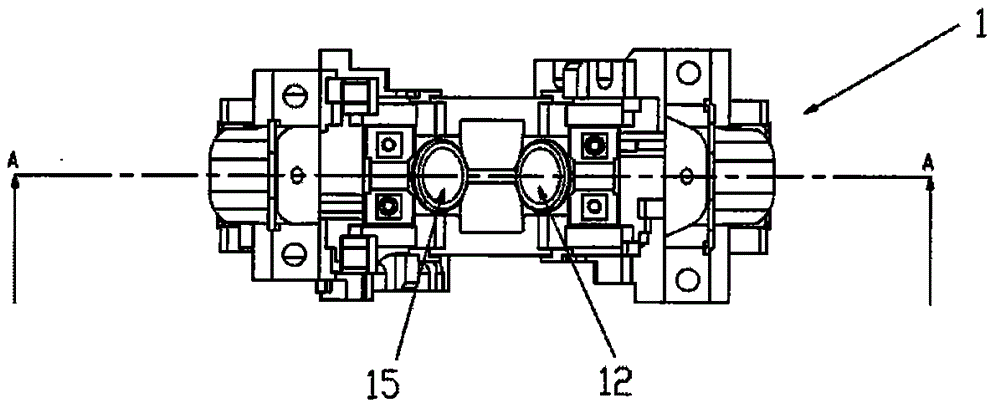

Image

  • Fiber welding method and fusion splicer
  • Fiber welding method and fusion splicer
  • Fiber welding method and fusion splicer

Examples


Embodiment Construction

[0043]Those skilled in the art will understand that unless otherwise stated, the singular forms "a", "an", "said" and "the" used herein may also include plural forms. It should be further understood that the word "comprising" used in the description of the present invention refers to the presence of said features, integers, steps, operations, elements and / or components, but does not exclude the presence or addition of one or more other features, Integers, steps, operations, elements, components, and / or groups thereof. It will be understood that when an element is referred to as being "connected" or "coupled" to another element, it can be directly connected or coupled to the other element or intervening elements may also be present. Additionally, "connected" or "coupled" as used herein may include wirelessly connected or coupled. As used herein, the term "and / or" includes any and all combinations of one or more of the associated listed items.

[0044] Those skilled in the art...


PUM


Abstract

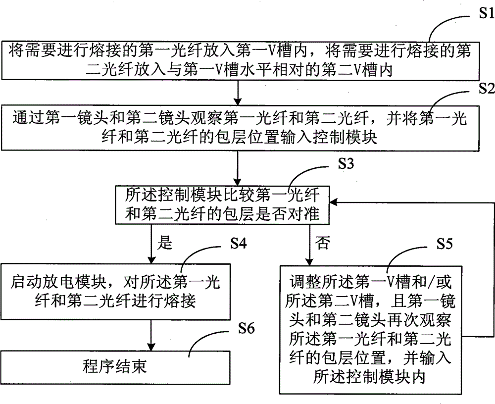
The invention discloses an optical fiber fusion splicing method and an optical fiber fusion splicing machine. The first optical fiber and the second optical fiber are observed through the first lens and the second lens, and the cladding positions of the first optical fiber and the second optical fiber are input into a control module; the control module Comparing whether the claddings of the first optical fiber and the second optical fiber are aligned; and adjusting the first V-groove and / or the second V-groove according to the comparison result of the cladding, so as to align the cores. The present invention realizes the adjustment of the fiber core through the alignment of the cladding, completes the core adjustment of the fiber without focusing the lens, performs more accurate fiber docking and construction, and ensures fusion splicing accuracy and low splicing loss. At the same time, Since there is no need for a lens to focus, there is no need for a motor for focusing, which realizes the miniaturization of the fusion splicer and reduces the cost of the fusion splicer.

Description

technical field [0001] The invention belongs to the technical field of optical communication, and in particular relates to an optical fiber fusion splicing method and an optical fiber fusion splicing machine. Background technique [0002] In optical communication, optical fiber fusion splicers are usually used for the construction and maintenance of optical cables. The working principle of the optical fiber fusion splicer is to use a high-voltage arc to melt the sections of two optical fibers, and at the same time use a motion mechanism to gently advance the two optical fibers into one, so as to realize the coupling of the optical fiber mode field. When merging optical fibers, the V-grooves of the two optical fibers are required to align the cores. [0003] In the prior art, there are many kinds of optical fiber fusion splicers according to different needs. According to different alignment methods, optical fiber fusion splicers are divided into mechanical fixed fusion spli...

Claims


Application Information

Patent Timeline
Patent Type & Authority Applications(China)
IPC IPC(8): G02B6/255
Inventor 赵阳日
Owner INNO INSTR (CHINA) INC
Why Eureka
Try Eureka