
Permanent magnet synchronous motor rotor assembly and permanent magnet synchronous motor

A technology for permanent magnet synchronous motors and components, which is applied to synchronous motors with stationary armatures and rotating magnets, magnetic circuit rotating parts, magnetic circuit shape/style/structure, etc., and can solve the problem of back electromotive force and air gap magnetic density High, application limitations of permanent magnet synchronous motors, ring magnet 3" cracking and other problems, to achieve the effect of improving back electromotive force and air gap flux density, preventing ring magnet cracking, and improving reliability

Inactive Publication Date: 2016-11-23
SHANGHAI HITACHI ELECTRICAL APPLIANCES CO LTD
View PDF5 Cites 1 Cited by
  • Summary
  • Abstract
  • Description
  • Claims
  • Application Information

AI Technical Summary

Problems solved by technology

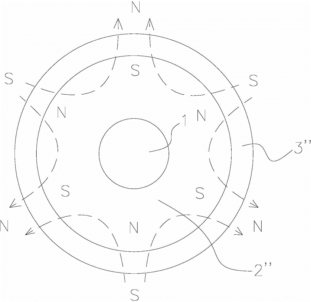
[0004] However, the output torque and output power of the existing permanent magnet synchronous motor and the counter electromotive force of the stator winding and the air gap magnetic density are not high, and, when the permanent magnet synchronous motor is running, due to the ring magnet 3 "and the rotor yoke 2 " (rotor The expansion coefficient of the iron core) is different and the magnet material is fragile and fragile. During the operation of the motor, the temperature rise or high-speed operation of the rotor assembly will cause the rupture of the ring magnet 3", which limits the size of the ring magnet 3", usually only Can be used in small power motors, which limits the application of permanent magnet synchronous motors

Method used


Image

  • Permanent magnet synchronous motor rotor assembly and permanent magnet synchronous motor
  • Permanent magnet synchronous motor rotor assembly and permanent magnet synchronous motor
  • Permanent magnet synchronous motor rotor assembly and permanent magnet synchronous motor

Examples


no. 1 example

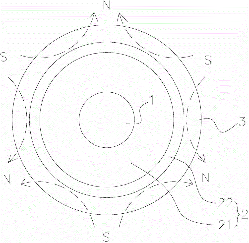
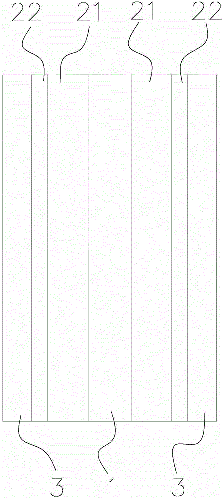
[0040] like figure 2 and image 3 As shown, it respectively shows a cross-sectional view and a longitudinal cross-sectional view of the rotor assembly of the permanent magnet synchronous motor of the present invention. Wherein, the cross-sectional view refers to a sectional view along the radial direction of the rotor assembly, and the longitudinal sectional view refers to a sectional view along the axial direction of the rotor assembly. exist figure 2 and image 3 In the preferred embodiment shown, the rotor assembly of the permanent magnet synchronous motor of the present invention includes: a rotating shaft 1 , a rotor yoke 2 and a multi-pole magnetic ring 3 .

[0041] The rotor yoke 2 is disposed around the outer periphery of the rotating shaft 1 . exist figure 2 and image 3 In the preferred example shown, the rotor yoke 2 includes a magnetically permeable portion 21 and a non-magnetically permeable portion 22 . The magnetically permeable part 21 is disposed aro...

no. 2 example

[0048] See Figure 7 , which shows a cross-sectional cross-sectional view of the rotor assembly of the permanent magnet synchronous motor of the second embodiment of the present invention. like Figure 7 As shown, the rotor assembly includes a rotating shaft 1 , a rotor yoke 2 and a multi-pole magnetic ring 3 . with the above figure 2 and image 3 The difference between the first embodiment shown in the above is that the rotor yoke part 2' only includes a non-magnetically conductive part 22' (excluding a magnetically conductive part), that is, the entire rotor yoke part 2' is made of a material that is flexible and cannot conduct magnetic fields (including but not limited to nitrile rubber material). Since the magnetic field lines of the magnetic field formed after the multi-pole magnetic ring 3 is magnetized rarely pass through the rotor yoke part in the multi-pole magnetic ring 3, the magnetic conducting part of the rotor yoke part plays a very small role. Therefore, in...


PUM


Abstract

The invention provides a permanent magnet synchronous motor rotor assembly and a permanent magnet synchronous motor. The permanent magnet synchronous motor rotor assembly comprises a rotating shaft, a rotor yoke which is arranged around the periphery of the rotating shaft and includes a non-magnetic part, and a multi-pole magnetic ring which is arranged around the periphery of the non-magnetic part of the rotor yoke. Through improvement made on the rotor yoke and the ring magnet part of the permanent magnet synchronous motor rotor assembly, the counter electromotive force and air gap flux density of the stator winding of the permanent magnet synchronous motor are improved effectively, and the output torque and output power of the permanent magnet synchronous motor are improved. Moreover, the problem that the ring magnet is broken during running of the permanent magnet synchronous motor due to the difference in material expansion coefficient between the ring magnet and the magnetic part of the rotor yoke in the prior art is prevented effectively, and the reliability of the permanent magnet synchronous motor is improved.

Description

technical field [0001] The invention relates to the field of motors, in particular to a rotor assembly of a permanent magnet synchronous motor and a permanent magnet synchronous motor with the rotor. Background technique [0002] The permanent magnet synchronous motor has the advantages of less loss, high efficiency and obvious power saving effect. The permanent magnet synchronous motor provides excitation with permanent magnets, which makes the motor structure relatively simple, reduces processing and assembly costs, and saves the collector ring and brush that are prone to problems, improving the reliability of the motor operation; and because no excitation is required Current, no excitation loss, improves the efficiency and power density of the motor, so it is a kind of motor that has been studied more in recent years and used more and more widely in various fields. Today, when energy saving and environmental protection are paid more and more attention, it is very necessa...

Claims


Application Information

Patent Timeline
Patent Type & Authority Applications(China)
IPC IPC(8): H02K1/27H02K21/14
Inventor 张兴志汪圣原范杰
Owner SHANGHAI HITACHI ELECTRICAL APPLIANCES CO LTD
Learn More