
Anti-low-frequency noise microphone unit

A low-frequency noise and microphone technology, which is applied in the field of microphone monomers, can solve problems such as the inability to collect voice signals, and achieve the effect of reducing sensitivity

Active Publication Date: 2016-11-23
ZILLTEK TECH SHANGHAI +1
View PDF9 Cites 7 Cited by
  • Summary
  • Abstract
  • Description
  • Claims
  • Application Information

AI Technical Summary

Problems solved by technology

However, the existing MEMS microphones include an acoustic diaphragm and a back plate opposite to the acoustic diaphragm. It is converted into an electrical signal output, but in actual use, the voice signal is usually accompanied by low-frequency noise signals (such as wind noise, car noise, etc.), and the microphone will absorb a large amount of noise in addition to collecting effective voice signals during the actual sound collection process. However, once the microphone diaphragm is saturated by the low-frequency noise signal, effective speech signals cannot be collected. For example, if a person speaks in the wind, the wind is too strong, which completely saturates the acquisition unit of the microphone (that is, the diaphragm is at the maximum In the amplitude state), the microphone cannot collect the voice signal from the person

Method used


Image

  • Anti-low-frequency noise microphone unit
  • Anti-low-frequency noise microphone unit

Examples


Embodiment Construction

[0024] The present invention will be further described below with reference to the drawings and specific embodiments, but it is not a limitation of the present invention.

[0025] The technical solutions in the embodiments of the present invention will be clearly and completely described below in conjunction with the accompanying drawings in the embodiments of the present invention. Obviously, the described embodiments are only a part of the embodiments of the present invention, rather than all the embodiments. Based on the embodiments of the present invention, all other embodiments obtained by those of ordinary skill in the art without creative work shall fall within the protection scope of the present invention.

[0026] It should be noted that the embodiments of the present invention and the features in the embodiments can be combined with each other if there is no conflict.

[0027] The present invention will be further described below with reference to the drawings and specific ...


PUM


Abstract

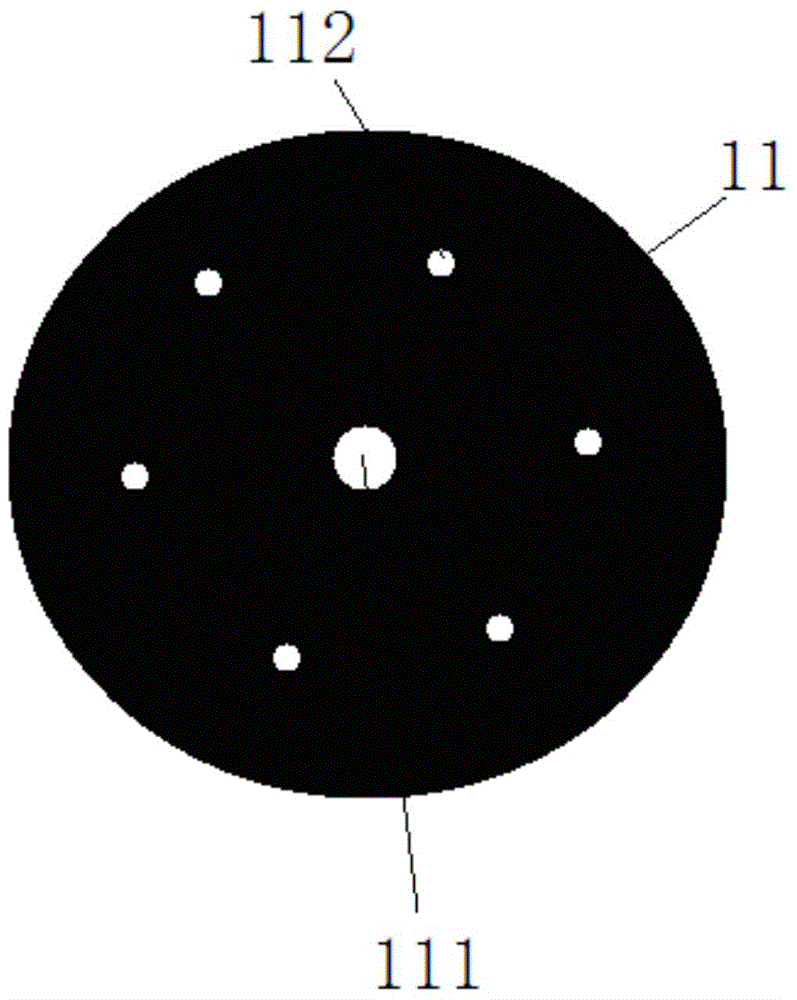
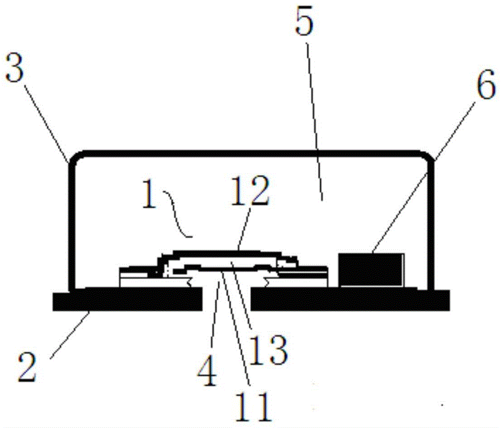
The invention belongs to the speech signal processing field and relates to an anti-low-frequency noise microphone unit. The anti-low-frequency noise microphone unit comprises an MEMS transducer and a back electrode; the MEMS transducer is provided with an acoustic vibrating diaphragm; a first through hole is formed at the center of the vibrating diaphragm; a plurality of second through holes which are used for relieving stress and far away from the first through hole are formed in the acoustic vibrating diaphragm; a fixed gap is left between the acoustic vibrating diaphragm and the back electrode; the acoustic vibrating diaphragm and the back electrode form a plate capacitor; and when the acoustic vibrating diaphragm is in a vibrating state, the plate capacitor generates capacitance signal output matched with the vibrating amplitude of the acoustic vibrating diaphragm according to the vibrating amplitude of the acoustic vibrating diaphragm. Compared with the prior art, and according to the anti-low-frequency noise microphone unit of the invention, the first through hole is formed at the center of the acoustic vibrating diaphragm, so that low-frequency noise signals can be filtered out.

Description

Technical field [0001] The invention relates to the technical field of speech signal processing, in particular to a microphone monomer capable of resisting low-frequency noise. Background technique [0002] At present, the market demand for consumer electronic products has increased sharply. Audio input devices are widely used in various electronic products, such as mobile phones, notebook computers, tablets, cameras, camcorders, etc., so a large number of microphones are required to be integrated into these products. [0003] At present, there are two main types of microphones on the market, one is ECM (Electret Condenser Microphone), and the other is MEMS (Micro Electro Mechanical System, Micro Electro Mechanical System) micro microphone. Because of its large size and high cost, ECM has been replaced by MEMS micro microphones in many occasions. Multiple microphones can be integrated on the same substrate and can be integrated with chips. Especially due to the difference in volum...

Claims


Application Information

Patent Timeline
Patent Type & Authority Applications(China)
IPC IPC(8): H04R19/04
Inventor 叶菁华
Owner ZILLTEK TECH SHANGHAI
Learn More