Air-conditioning device and installation method thereof
An air-conditioning device and space technology, applied in air-conditioning systems, heating methods, lighting and heating equipment, etc., can solve the problem of long refrigerant piping and achieve the effect of not damaging safety
- Summary
- Abstract
- Description
- Claims
- Application Information
AI Technical Summary
Problems solved by technology
Method used
Image
Examples
Embodiment approach 1
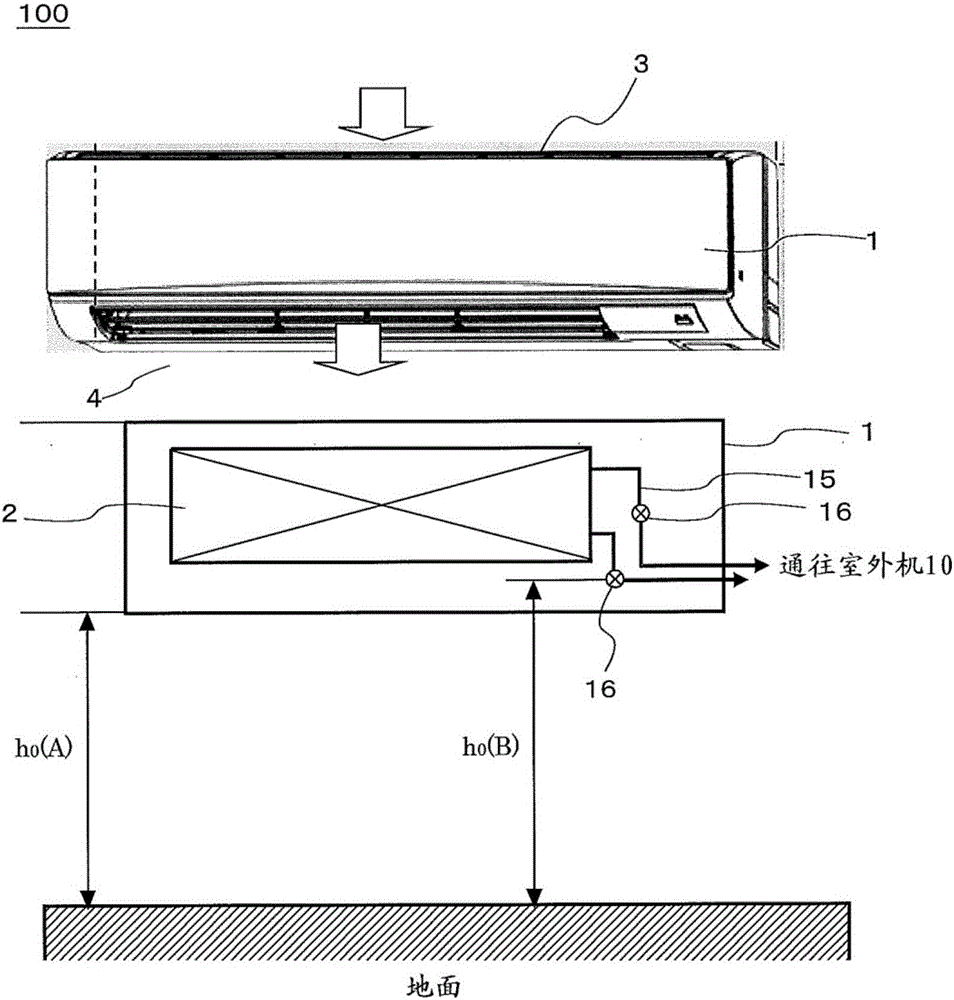
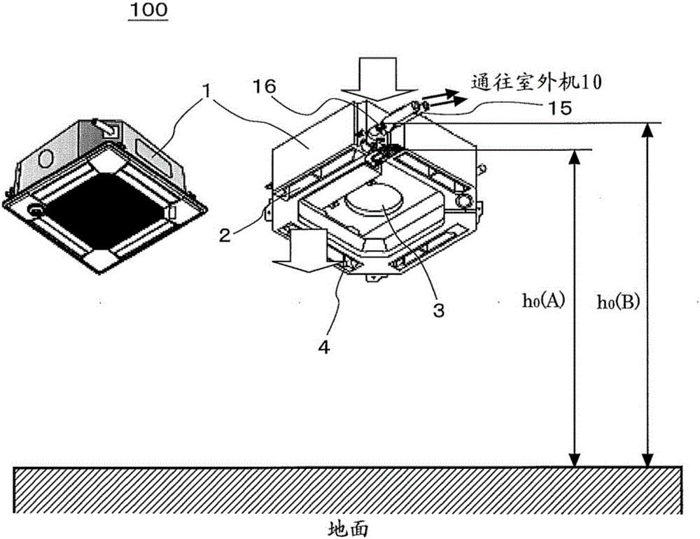
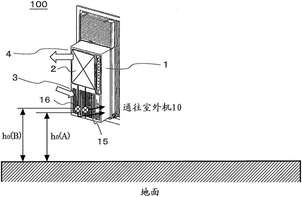
[0028] figure 1 It is a schematic diagram showing an example of an indoor unit constituting the air conditioner (hereinafter referred to as the air conditioner 100 ) according to Embodiment 1 of the present invention. figure 2 It is a schematic diagram showing another example of the indoor unit constituting the air conditioner 100 . image 3 It is a schematic diagram showing still another example of the indoor unit constituting the air conditioner 100 . Figure 4 It is a schematic diagram showing still another example of the indoor unit constituting the air conditioner 100 . Figure 5 It is a schematic configuration diagram showing the refrigerant circuit configuration of the air conditioner 100 . based on Figure 1 to Figure 5 , the air conditioner 100 will be described centering on the indoor unit.
[0029] The air conditioner 100 is assumed to use a flammable refrigerant, with Figure 1 to Figure 4 The illustrated indoor unit 1 and an outdoor unit 10 connected to the ...
Embodiment 1
[0064] Tables 1 to 9 are for installing the wall-mounted indoor unit 1 so that the ground height of the lower end is 1.8m, and the floor space is 12m. 2 、36m 2 、64m 2, a wall surface of a confined space 50 with a ceiling height of 2.5m, and the leakage refrigerant amount is 0.5-70.0kg, the average leakage velocity V is 5kg / h, 10kg / h, 75kg / h, and the ground height of the gas concentration sensor is In the case of 50mm, 100mm, 250mm, 500mm, 1000mm, 1500mm, and 2000mm, the investigation of the occurrence of combustible area when R32 leaks.
[0065] [Table 1]
[0066]
[0067] [Table 2]
[0068]
[0069] [table 3]
[0070]
[0071] [Table 4]
[0072]
[0073] [table 5]
[0074]
[0075] [Table 6]
[0076]
[0077] [Table 7]
[0078]
[0079] [Table 8]
[0080]
[0081] [Table 9]
[0082]
[0083] To organize the above examples, the allowable refrigerant amount (M upper limit) and the m based on IEC60335-2-40 do not appear in the flammable area ...
Embodiment 2
[0104] The ceiling-type indoor unit 1 is installed in such a way that the ground height of the lower end is 2.2m, and the floor space is 12m. 2 、36m 2 、64m 2 The central part of the ceiling of the closed space 50, and the leakage refrigerant amount is 0.5 ~ 53.4kg, the average leakage velocity V is 5kg / h, 10kg / h, 75kg / h, and the height of the gas concentration sensor above the ground is 50mm, 100mm, 250mm , 500mm, 1000mm, 1500mm, and 2000mm, the results of the same investigation on the occurrence of combustible regions in the case of leaking R32 are shown in Table 11.
[0105] [Table 11]
[0106] h 0 = 2.2[m] M upper limit or m max (in brackets is m max / A or Mcap / A)
[0107]
[0108] Thus, the same phenomenon as in Example 1 occurs, at h 0 =2.2[m], when G=5[kg / h], (the maximum value of M / A)=1.30[kg / m 2 ], G=10[kg / h], (the maximum value of M / A)=0.925[kg / m 2 ], G=75[kg / h], (the maximum value of M / A)=0.423[kg / m 2 ] can be.
PUM
| Property | Measurement | Unit |
|---|---|---|
| Height | aaaaa | aaaaa |
Abstract
Description
Claims
Application Information
 - R&D
- Intellectual Property
- Life Sciences
- Materials
- Tech Scout
- Unparalleled Data Quality
- Higher Quality Content
- 60% Fewer Hallucinations
Browse by: Latest US Patents, China's latest patents, Technical Efficacy Thesaurus, Application Domain, Technology Topic, Popular Technical Reports.
© 2025 PatSnap. All rights reserved.Legal|Privacy policy|Modern Slavery Act Transparency Statement|Sitemap|About US| Contact US: help@patsnap.com


