Actuator drive

A driving device and actuator technology, applied in emergency protection circuit devices, AC motor control, control systems, etc., can solve problems such as equipment failures, and achieve the effects of improving safety, reducing costs, and simple structure

Active Publication Date: 2018-03-30
DAIKIN IND LTD
View PDF8 Cites 0 Cited by
  • Summary
  • Abstract
  • Description
  • Claims
  • Application Information

AI Technical Summary

Problems solved by technology

In particular, equipment used in areas where power supply voltage fluctuations are likely to occur

Method used


Image

  • Actuator drive
  • Actuator drive
  • Actuator drive

Examples


Embodiment Construction

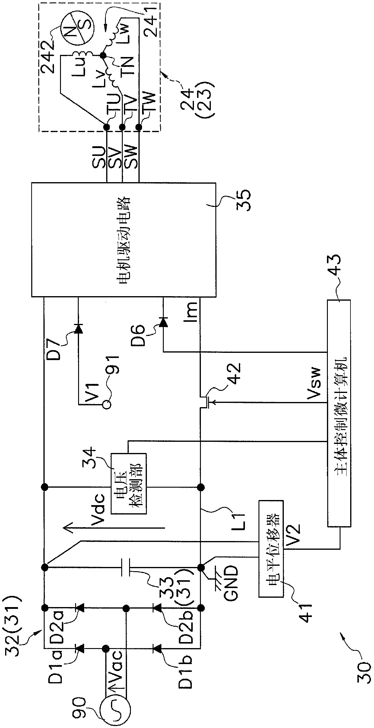
[0053] Hereinafter, a motor drive device 30 according to an embodiment of the present invention will be described with reference to the drawings. In addition, the following embodiment is a specific example of this invention, It does not limit the technical scope of this invention, It can change suitably in the range which does not deviate from the summary of invention.

[0054] The motor drive device 30 in this embodiment is mounted on the air conditioner 100 . Specifically, the motor driving device 30 is a device that controls the driving of the indoor fan motor 23 (motor portion 24 ), one of the actuators included in the air conditioner 100 .

[0055] (1) Air conditioner 100

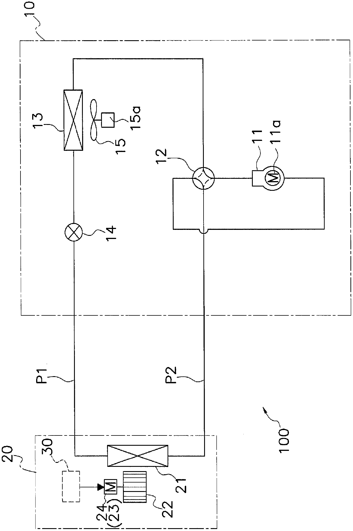
[0056] figure 1 It is a schematic configuration diagram of an air conditioner 100 equipped with a motor drive device 30 according to an embodiment of the present invention.

[0057] The air conditioner 100 is a device that performs a cooling operation or a heating operation to air-condition a target...


PUM


Abstract

In a motor drive device (30), a motor drive unit (38) outputs drive voltages (SU, SV, SW) to a motor portion (24). A switching unit (42) switches between the conduction and disconnection of a GND wire (L1) connecting the lower potential side of the motor drive unit (38) and a DC voltage generation unit (31). A body control microcomputer (43) controls the operation of the motor drive unit (38). The body control microcomputer (43) controls the operation of the switching unit (42) such that when a voltage value detected by a voltage detection unit (34) is less than a first threshold value (ΔTh1), the GND wire (L1) is made conductive and when the voltage value is greater than or equal to the first threshold value (ΔTh1), the GND wire (L1) is disconnected. A first reverse current prevention diode (D6) is disposed between the motor drive unit (38) and the body control microcomputer (43) and prevents current from flowing from the DC voltage generation unit (31) to the body control microcomputer (43) through the motor drive unit (38) when the GND wire (L1) is disconnected by the switching unit (42).

Description

technical field [0001] The invention relates to devices for driving actuators. Background technique [0002] In a device that rectifies an AC voltage to obtain a DC voltage, the DC voltage fluctuates according to the AC voltage. In particular, equipment used in areas where fluctuations in power supply voltage are likely to occur may cause equipment failure depending on how countermeasures are taken when the voltage rises. Therefore, the overvoltage protection unit disclosed in Patent Document 1 (Japanese Patent Laid-Open No. 2007-166815) is provided. This overvoltage protection unit uses the input transformer as the transformer of the on-load tap changer, and switches the taps of the transformer of the on-load tap changer when a voltage above a certain threshold is input to the inverter for more than a predetermined time to the low pressure side. Contents of the invention [0003] The problem to be solved by the invention [0004] However, the above-mentioned transform...

Claims


Application Information

Patent Timeline
IPC IPC(8): H02M7/48H02H7/122H02P27/06
CPCH02H7/122H02M7/48H02P27/06
Inventor 佐藤俊彰矢吹俊生田口泰贵畑山敬之
Owner DAIKIN IND LTD
Why Eureka
Try Eureka