Load carrier and pressure spring for the upper roller of the drafting unit

A technology of drafting device and pressure spring, which is applied in the direction of drafting equipment, textiles, papermaking, spinning machines, etc., can solve the problems of unsatisfactory textile results and disadvantages, and achieve the effect of simple fixing possibility and uniform fiber strands

Active Publication Date: 2021-03-30
MASCHINENFABRIK RIETER AG
View PDF5 Cites 0 Cited by
  • Summary
  • Abstract
  • Description
  • Claims
  • Application Information

AI Technical Summary

Problems solved by technology

The disadvantage here is that the pressure of the load arm directed towards the upper delivery roller has to be distributed over the upper delivery roller as well as the clamping rollers
This results in unfavorable pressure ratios in some applications which lead to unfavorable textile results

Method used


Image

  • Load carrier and pressure spring for the upper roller of the drafting unit
  • Load carrier and pressure spring for the upper roller of the drafting unit

Examples


Embodiment Construction

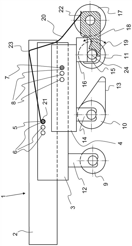
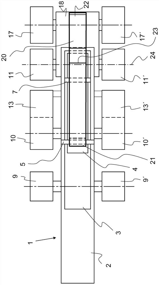
[0029] exist figure 1 A longitudinal section through a load carrier 1 according to the invention is shown in . The load carrier 1 has a guide rail 2 , a first bridge 3 and a second bridge 4 . The first bridge portion 3 is provided on the guide rail 2 in a rotatable manner by means of a rotary shaft 5 . The axis of rotation 5 is thus fixed in one of the three openings 6 and thus causes the first bridge 3 to be rotatably mounted in the guide rail 2 . The second bridge 4 is rotatably connected to the first bridge 3 via a further axis of rotation 7 in one of the three openings 8 . The openings 6 and 8 are preferably provided correspondingly in the first bridge part 3 and the guide rail 2 or in the second bridge part 4 and the first bridge part 3 in order to induce the rotation shaft 5 or the rotation shaft 7 as a first bridge The connection between the part 3 and the guide rail 2 or the connection between the second bridge part 4 and the first bridge part 3 . Depending on the po...


PUM


Abstract

In a load carrier for upper rollers of a drafting syste of a spinning machine, the upper rollers consist of an inlet roller, a middle roller and an outlet roller of the drafting system. The load carrier has a guide rail and at least one bridge rotatably supported in the guide rail about a shaft of rotation, at least one of the upper rollers of the drafting syste is fixed on the bridge. A transmission device is arranged on the bridge, and the outlet roller of the drafting system and a clamping roller of a compression device are arranged in the transmission device and are connected to each other in a transmitting manner. The guide rail and / or the bridge has at least one opening in which the shaft of rotation is accommodated. The output roller is arranged on the bridge in particular by means of a loading device. The clamping roller is arranged iin an opening of the guide rail and / or the bridge via a pressure spring load and the pressure spring and preferably on the shaft of rotation. The pressure spring has an accommodating part used for a fixing purpose on the guide rail, a pressure surfac for loading a clamping roller at a working position, and a stop surface for enabling the pressure spring to be supported on the guide rail of the load carrier at the working position.

Description

technical field [0001] The invention relates to a load carrier for an upper roller of a drafting device of a spinning machine and to a pressure spring for such a load carrier, wherein the upper roller forms an input roller, an intermediate roller of a drafting device And output roller, it has guide rail and at least one bridge part (Brücke) that can be rotatably supported around the rotation axis in this guide rail, at least one upper roller of drafting device is fixed on this bridge part and wherein in this bridge A transmission device is arranged on the part, and the output roller of the drafting device and the pinch roller of the compacting device are arranged in the transmission device and are connected to each other in a driving manner, and wherein the guide rail and / or the bridge part has at least one opening, and the rotating shaft is accommodated in the transmission device. In the opening and the output rollers are arranged on the bridge by means of load means. Backg...

Claims


Application Information

Patent Timeline
Patent Type & Authority Patents(China)
IPC IPC(8): D01H5/74D01H5/50D01H13/00D02J1/04
CPCD01H5/50D01H5/74D01H13/00D02J1/04D01H5/505D01H5/565D01H5/72D01H5/82
Inventor K·胡贝尔
Owner MASCHINENFABRIK RIETER AG
Why Eureka
Try Eureka