Rapidly-cooling pressure cooking appliance

A technology for rapid cooling and cooking utensils, applied to pressure cookers, etc., can solve the problems of water leakage, insufficient safety, inconvenient disassembly and cleaning of the inner cover of the pot cover, etc., to achieve convenient use, improve cooking efficiency, and shorten the time to open the pot cover the effect of time

Active Publication Date: 2016-12-07
PANASONIC APPLIANCES CHINA CO LTD +1
View PDF7 Cites 69 Cited by
  • Summary
  • Abstract
  • Description
  • Claims
  • Application Information

AI Technical Summary

Problems solved by technology

This cooling method will increase the weight of the inner cover, which is not convenient for disassembly and cleaning of the inner cover of the pot
[0005] In the prior art, some electric pressure cooker products also adopt the water-cooling method of the inner pot to achieve rapid pressure reduction. Some directly spray water on the inner pot to cool down, and some use cooling pipes to cool down the inner pot. The water-cooling method has water leakage. Hidden danger, once water leaks, it may cause a short circuit, and the safety is not high enough; the way of cooling the cooling tube also has problems such as high cost and inconvenient use

Method used


Image

  • Rapidly-cooling pressure cooking appliance
  • Rapidly-cooling pressure cooking appliance
  • Rapidly-cooling pressure cooking appliance

Examples


Embodiment 1

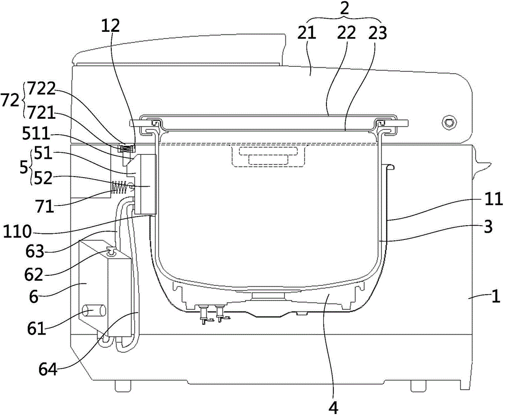
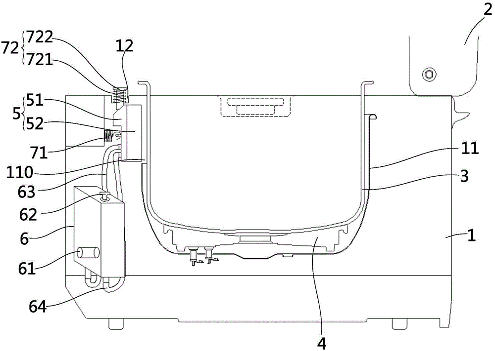
[0034] refer to figure 1 , 2 , the pressure cooking appliance of the embodiment of the present invention includes a body 1, a cover body 2 and an inner pot 3, the body 1 includes an outer pot 11, the inner pot 3 is accommodated in the outer pot 11 and can be taken out from the outer pot 11, and the cover body 2 It is hingedly connected to the body 1, and the cover body 2 can be flipped around its hinge. Specifically: in the pressure cooking appliance described in this embodiment, the cover body 2 includes an outer cover 21, an inner cover 23, and a lock ring 22 arranged between the outer cover 21 and the inner cover 23 and which can rotate relative to the inner cover 23. The ring 22 is provided with a first locking tooth, and the edge of the inner pot 3 is provided with a second locking tooth. When the cover body 2 is flipped and closed, rotating the locking ring 22 can make the first locking tooth and the second locking tooth snap together. The inner cover 23 is sealed with...

Embodiment 2

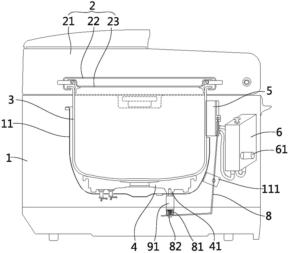
[0051] refer to image 3 The pressure cooking appliance proposed in this embodiment includes a body 1, a cover body 2 and an inner pot 3, the body 1 includes an outer pot 11, the inner pot 3 is accommodated in the outer pot 11 and can be taken out from the outer pot 11, and the cover body 2 It is hingedly connected to the body 1, and the cover body 2 can be flipped around its hinge. Specifically: in the pressure cooking appliance described in this embodiment, the cover body 2 includes an outer cover 21, an inner cover 23, and a lock ring 22 arranged between the outer cover 21 and the inner cover 23 and which can rotate relative to the inner cover 23. The ring 22 is provided with a first locking tooth, and the edge of the inner pot 3 is provided with a second locking tooth. When the cover body 2 is flipped and closed, rotating the locking ring 22 can make the first locking tooth and the second locking tooth snap together. The inner cover 23 is sealed with the inner pot 3 to fo...

Embodiment 3

[0057] refer to Figure 4 , 5 The pressure cooking appliance proposed in this embodiment includes a body 1, a cover body 2 and an inner pot 3, the body 1 includes an outer pot 11, the inner pot 3 is accommodated in the outer pot 11 and can be taken out from the outer pot 11, and the cover body 2 It is hingedly connected to the body 1, and the cover body 2 can be flipped around its hinge. Specifically: in the pressure cooking appliance described in this embodiment, the cover body 2 includes an outer cover 21, an inner cover 23, and a lock ring 22 arranged between the outer cover 21 and the inner cover 23 and which can rotate relative to the inner cover 23. The ring 22 is provided with a first locking tooth, and the edge of the inner pot 3 is provided with a second locking tooth. When the cover body 2 is flipped and closed, rotating the locking ring 22 can make the first locking tooth and the second locking tooth snap together. The inner cover 23 is sealed with the inner pot 3...


PUM


Abstract

The invention discloses a rapidly-cooling pressure cooking appliance, and belongs to the field of kitchen cooking electric appliances. The technical problem that an existing pressure cooking appliance can not be rapidly opened after cooking is completed is solved. A rapidly-cooling electric pressure cooker comprises a body, an inner cooker body, a cover and a cooling mechanism, wherein the body comprises an outer cooker body; the inner cooker body is contained in the outer cooker body; the body is covered with the cover, and the cover and the inner cooker body can form a pressure cooking cavity in a sealed mode; the cooling mechanism comprises a cooler, a driving device and a cooling medium container for storing cooling media, the cooling media can be led into the cooler through the cooling medium container, and the driving device drives the cooler to be in contact with the inner cooker body or separated from the inner cooker body. The embodiment of the rapidly-cooling pressure cooking appliance is applied to kitchen pressure cooking appliances such as electric pressure cooker products and pressure cooker products.

Description

【Technical field】 [0001] The invention relates to a rapidly cooling pressure cooking appliance, which belongs to the field of kitchen cooking appliances. 【Background technique】 [0002] In order to adapt to people's fast-paced modern life, current kitchen cooking utensils are developing in a fast and convenient direction. The existing known electric pressure cooker is widely liked by people because it can cook quickly and the food it cooks has less nutritional loss, and it has become one of the fast-growing electrical appliances in the household appliance industry with time-saving, power-saving, convenience and quickness. However, the traditional electric pressure cooker cannot enjoy the food immediately because the lid of the pot cannot be quickly opened after fast cooking, which has become the biggest problem for users of the electric pressure cooker. [0003] In order to solve the technical problem that the traditional electric pressure cooker cannot be quickly opened, t...

Claims


Application Information

Patent Timeline
Patent Type & Authority Applications(China)
IPC IPC(8): A47J27/08A47J27/09
Inventor 朱光正乐晓辉
Owner PANASONIC APPLIANCES CHINA CO LTD
Why Eureka
Try Eureka