
a deburring machine

A technology of deburring machine and frame, which is applied to grinding frames, parts of grinding machine tools, machine tools suitable for grinding workpiece edges, etc., can solve the problems of long time required, low working efficiency of deburring machines, Problems such as low efficiency of transposition

Active Publication Date: 2018-10-02
HUBEI AVIATION PRECISION MASCH TECH CO LTD
View PDF8 Cites 0 Cited by
  • Summary
  • Abstract
  • Description
  • Claims
  • Application Information

AI Technical Summary

Problems solved by technology

However, each transposition requires a larger angle of swing of the pendulum to be realized, and the time required for each swing is longer, and the efficiency of transposition is low, resulting in low work efficiency of the deburring machine

Method used


Image

  • a deburring machine
  • a deburring machine
  • a deburring machine

Examples


Embodiment Construction

[0075] The core of the present invention is to provide a deburring machine, whose transposition mechanism realizes the movement of the workpiece from the current station to the next station through the intermittent divider, which greatly improves the transposition efficiency of the workpiece, and then improves the work of the deburring machine efficiency.

[0076] In order to enable those skilled in the art to better understand the technical solutions of the present invention, the present invention will be further described in detail below in conjunction with the accompanying drawings and specific embodiments.

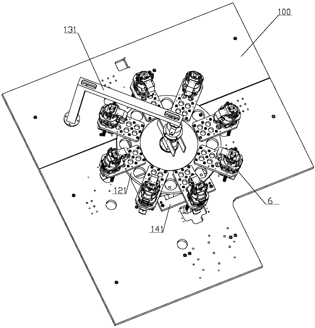
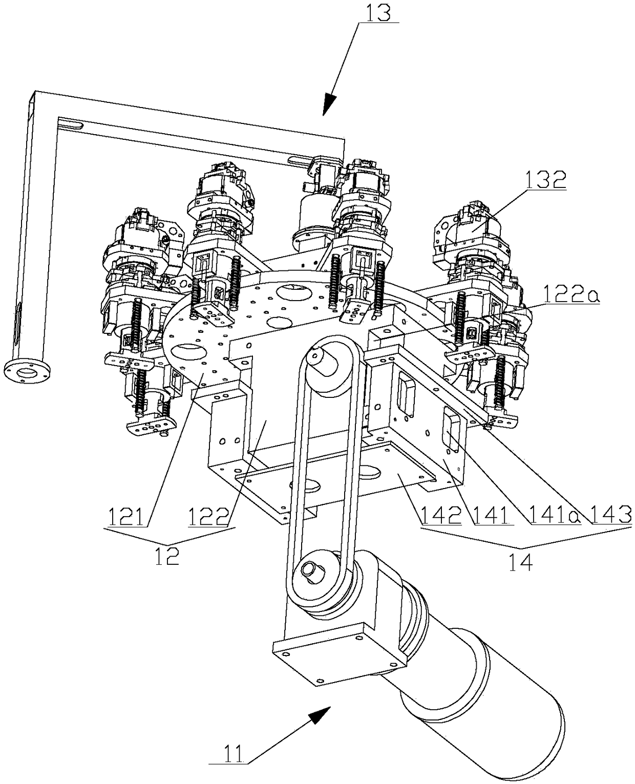
[0077] It should be noted that the orientation word "top" in this article refers to image 3 The upper end of the, "bottom end" refers to the image 3 The lower end of ; the orientation words "front, back, right, left, up, and down" appearing in this article are shown in other figures. It should be understood that these orientation words are established based on the ...


PUM


Abstract

The invention discloses a deburring machine. The deburring machine includes a frame, and the frame is provided with a plurality of stations; The device includes a turntable that can intermittently index and rotate in the horizontal plane, and a plurality of clamps for clamping workpieces are uniformly distributed on the circumference of the turntable; The clamps are set correspondingly. The above-mentioned intermittent divider is used as the transposition device, so that the deburring operation can be completed every time the turntable rotates a small angle. Compared with the four-link transposition mechanism in the prior art, this transposition mechanism greatly improves the transposition bit efficiency, thereby improving the work efficiency of the deburring machine.

Description

technical field [0001] The invention relates to the technical field of machining, in particular to a deburring machine. Background technique [0002] After stamping, stamping parts will have burrs on the punching section, which will affect the function of the product. These burrs need to be removed. [0003] Please refer to figure 1 , figure 1 It is a structural schematic diagram of the transposition mechanism of the deburring machine in the prior art. [0004] In the existing technology, such as figure 1 As shown, the deburring machine includes a frame 200', and the frame 200' is provided with four stations 300'. The transposition mechanism comprises a driving device, a transport frame 42' and at least two clamping devices 43'. [0005] The transmission frame 42' is a link mechanism that can reciprocate relative to the frame 200'. The link mechanism includes at least two swing bars 421' arranged in parallel. The bottom ends of the swing bars 421' are hinged to the fram...

Claims


Application Information

Patent Timeline
Patent Type & Authority Patents(China)
IPC IPC(8): B24B9/04B24B27/00B24B41/00B24B41/02B24B41/06B24B55/06B23P23/04B23Q7/02
CPCB23P23/04B23Q7/02B24B9/04B24B27/0023B24B27/0069B24B41/005B24B41/02B24B41/06B24B55/06
Inventor 黄正坤胡冠之
Owner HUBEI AVIATION PRECISION MASCH TECH CO LTD
Learn More