Aero engine fan blade lever device

A technology for aero-engines and fan blades, applied in hand-held tools, manufacturing tools, etc., can solve problems such as waste of manpower, inconvenient adjustment, danger, etc., and achieve the effects of easy storage and transportation, increased distance, and quick installation and disassembly

Active Publication Date: 2017-09-19
成都航利装备科技有限公司
View PDF3 Cites 0 Cited by
  • Summary
  • Abstract
  • Description
  • Claims
  • Application Information

AI Technical Summary

Problems solved by technology

During routine inspection and maintenance engine inspection, one person needs to manually rotate the high-pressure rotor outside, and one person observes the blades at the front end of the engine. Two people are required to cooperate to complete the inspection work. The adjustment is very inconvenient and requires a ladder, which is dangerous and wasteful. manpower

Method used


Image

  • Aero engine fan blade lever device
  • Aero engine fan blade lever device
  • Aero engine fan blade lever device

Examples


Embodiment Construction

[0020] The present invention will be further described below in conjunction with the accompanying drawings, but the protection scope of the present invention is not limited to the following description.

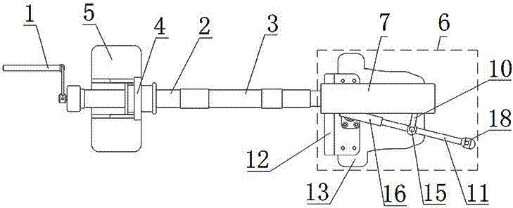
[0021] Such as figure 1 As shown, the aeroengine fan blade lever device includes a handle 1, a front pipe section 2, a rear pipe section 3, a bracket A4, a base plate A5 and a drive mechanism 6, and the handle 1 is connected to one end of the front pipe section 2, and a There is an overrunning clutch to limit the counterclockwise rotation of the handle; there is a bracket A4 on the front pipe section 2 near the connection, and the bracket A4 is fixed on the bottom plate A5 through a dovetail chute; the other end of the front pipe section 2 and one end of the rear pipe section 3 The other end of the rear pipe section 3 is connected with the driving mechanism 6 through the connecting shaft 14 .

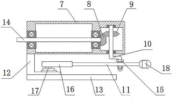
[0022] Such as figure 2 As shown, the driving device 6 includes a driving housi...


PUM


Abstract

The invention discloses a deflector rod device for an aircraft engine fan blade, which comprises a handle, a front pipe section, a rear pipe section, a bracket A, a bottom plate A and a driving mechanism, wherein the handle is connected with one end of the front pipe section; an overrunning clutch is arranged at the joint of the handle and the front pipe section, and is used for limiting anticlockwise rotation of the handle; the bracket A is arranged at a position, near the joint, of the front pipe section, and is fixed on the bottom plate A via a dovetail-type chute; the other end of the front pipe section is connected with one end of the rear pipe section; and the other end of the rear pipe section is connected with the driving mechanism via a connecting shaft. The deflector rod device has the advantages of being simple in structure, easy to disassemble, and convenient for long-distance toggling of the aircraft engine fan blade.

Description

technical field [0001] The invention relates to the technical field of routine inspection and maintenance of aero-engines, in particular to a fan blade lever device of an aero-engine. Background technique [0002] A special maintenance tool for the fan blade of an aero-engine similar to the present invention is found after retrieval. During routine inspection and maintenance engine inspection, one person needs to manually rotate the high-pressure rotor outside, and one person observes the blades at the front end of the engine. Two people are required to cooperate to complete the inspection work. The adjustment is very inconvenient and requires the help of a ladder, which is dangerous and wasteful. manpower. Contents of the invention [0003] The purpose of the present invention is to overcome the disadvantages of the prior art and provide an aeroengine fan blade lever device with simple structure, easy disassembly and convenient remote operation. [0004] The object of t...

Claims


Application Information

Patent Timeline
Patent Type & Authority Patents(China)
IPC IPC(8): B25B33/00
CPCB25B33/00
Inventor 刘华平王军蔡远思古云祥叶志远罗鸣
Owner 成都航利装备科技有限公司
Why Eureka
Try Eureka