Detachable steel core die and method for manufacturing prestress concrete hollow beam
A technology of steel core and the other side, applied in the direction of joists, girders, trusses, etc., can solve the problems of not disclosing the specific structure of the abrasive tool, inconvenient disassembly of the mold, etc., to improve the fullness and compactness, and improve durability. Effect
- Summary
- Abstract
- Description
- Claims
- Application Information
AI Technical Summary
Problems solved by technology
Method used
Image

Examples
Embodiment 1
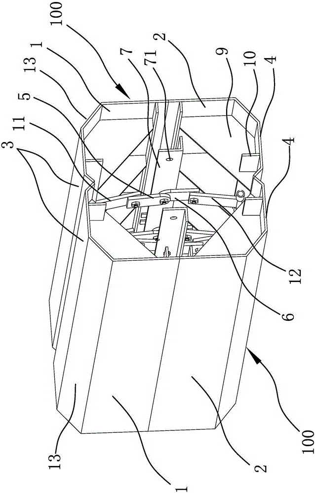
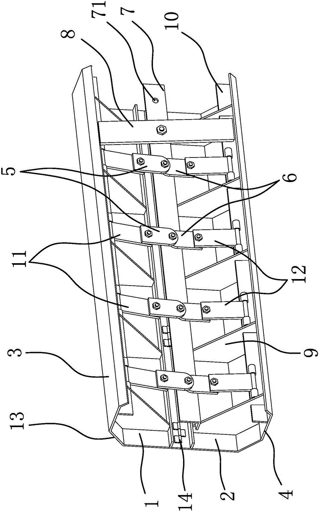
[0037] Such as figure 1 and figure 2 As shown, the detachable steel mandrel includes two support assemblies 100, and each support assembly 100 includes a strip-shaped petal body 1 and a strip-shaped petal body 2 2, and one side of the petal body 1 is connected to the petal body 1. One side of the body two 2 is hinged by a hinge 14, and the other side of the petal body one 1 and the other side of the petal body two 2 respectively have a plate body one 3 and a plate body two 4 bent in the same direction. Body one 3 and plate body two 4 are arranged oppositely, and plate body one 3 is hinged with a number of connecting arms one 5 facing plate body two 4 near the outer edge, and plate body two 4 is hinged near the outer edge with several connecting arms one 5 corresponding to each other. Connecting arm two 6, plate body one 3 and plate body two 4 are also provided with pull bar 7 along the length direction of petal body one 1 and petal body two 2, the ends of connecting arm one ...
Embodiment 2
[0042] This embodiment is a method for making a prestressed concrete hollow beam using the detachable steel mandrel in Embodiment 1. The method includes the following steps:
[0043] a. Install the steel frame: Build the steel frame on the flat ground, the steel frame is in the shape of a long strip, and the cross section of the steel frame is in the shape of a "mouth";
[0044] b. Install the peripheral board: fix the peripheral board on both sides of the steel frame, and the peripheral board is attached to the outer surface of the steel frame;
[0045] c. Install the corrugated pipe: fix the corrugated pipe in the steel frame, the bellows are arranged along the length direction of the steel frame, the bellows are distributed on both sides of the steel frame, and the two ends of the bellows protrude from the end of the steel frame;
[0046] d. Install the anchor seat: fix the anchor seat at both ends of the steel frame, position and fix the anchor seat with the positioning st...
PUM
 Abstract
Description
Claims
Application Information