
Hot plate type giant tire vulcanizing equipment

A hot plate and equipment technology, which is applied in the field of hot plate giant tire vulcanization equipment, can solve the problems of bulky size and complex structure, and achieve the effects of compact equipment structure, high heating efficiency, and improved orientation and positioning

Active Publication Date: 2016-12-07
HIMILE MECHANICAL SCI & TECH (SHANDONG) CO LTD
View PDF6 Cites 2 Cited by
  • Summary
  • Abstract
  • Description
  • Claims
  • Application Information

AI Technical Summary

Problems solved by technology

[0006] For the problems in the prior art, the invention provides a hot plate type giant tire vulcanization equipment, which solves the problem of large volume and complex structure of the opening and closing mold equipment of the giant tire vulcanization equipment, further solves the vulcanization heating method, improves the installation and coordination of the mold, and adopts Clamping mechanism improves vulcanization efficiency

Method used


Image

  • Hot plate type giant tire vulcanizing equipment
  • Hot plate type giant tire vulcanizing equipment
  • Hot plate type giant tire vulcanizing equipment

Examples


Embodiment 1

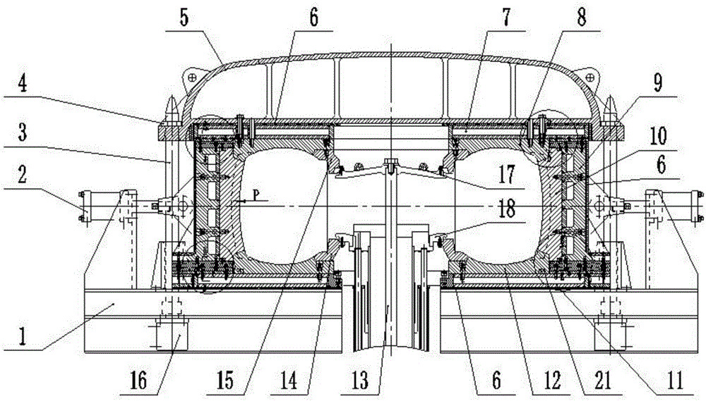
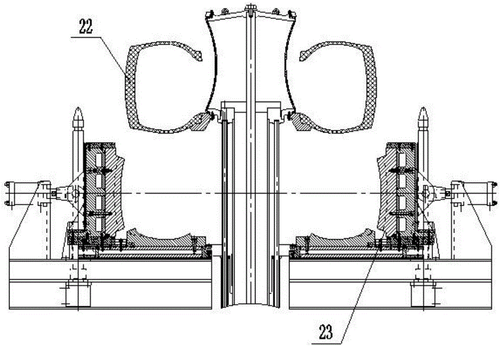
[0061] The giant tire mold includes an upper steel ring 15 and a lower steel ring 14, the upper steel ring 15 is matched with the upper side plate 8, the lower steel ring 14 is matched with the lower side plate 12, and the middle of the base 1 is set as hollow Structure, the hollow structure is provided with a central mechanism 13, and a capsule chuck on the top of the central mechanism 13, the capsule chuck includes a capsule upper chuck 17 and a capsule lower chuck 18, the capsule upper chuck 17 The lower chuck 18 and the lower capsule 18 cooperate with the upper steel ring 15 and the lower steel ring 14 to clamp the upper and lower edges of the capsule.

[0062] During vulcanization, the block 10 is opened by the slider 9 in the radial direction of the slider guide key 902 under the action of the block opening and closing drive device 2 to remove the upper side plate 8, and the center mechanism 13 drives the lower steel ring 14, the capsule The upper chuck 17 and the lower cap...

Embodiment 2

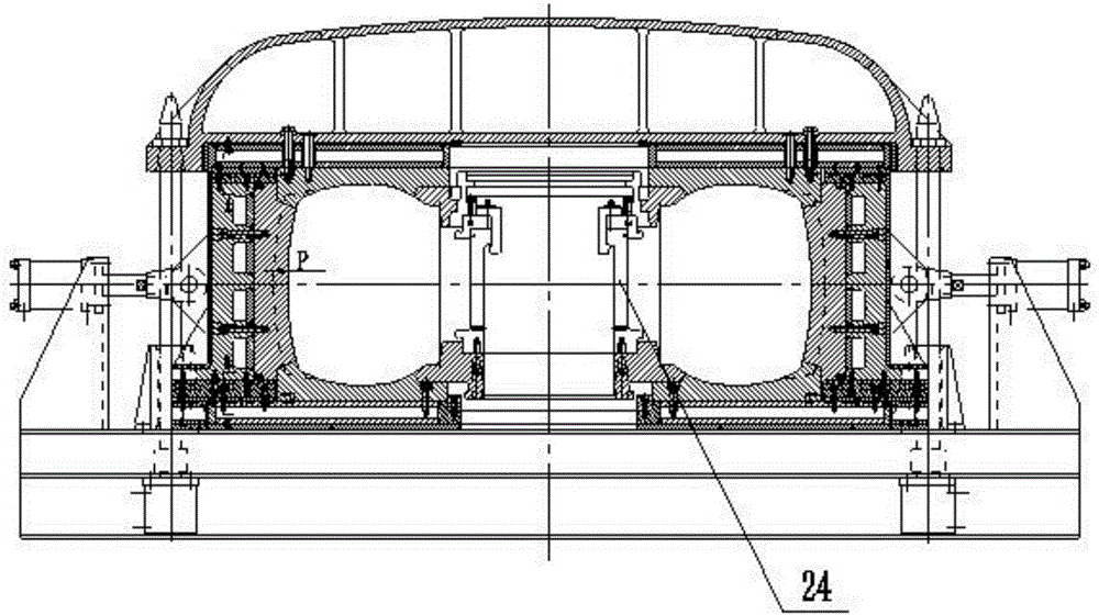
[0065] The same parts as in the first embodiment will not be repeated, such as image 3 , Figure 4 As shown, a clamping mechanism 24 is provided between the upper steel ring 15 and the lower steel ring 14. The clamping mechanism 24 includes an upper clamping ring 242 and a lower clamping ring 241. The lower clamping ring 241 and the lower steel ring 14 is matched, the upper clamping ring 242 is provided with a locking ring 243, the locking ring 243 is matched with the upper steel ring 15, and the upper clamping ring 242 and the lower clamping ring 241 are also provided with a securing block 244. This structure does not require an additional central mechanism 13, which saves costs.

[0066] During vulcanization, the upper side plate 8 is removed. After the tire blank 22 is installed on the external shaping equipment, it is fixed on the locking ring 243 with a lifting mechanism, and the clamping mechanism 24, the capsule and the tire blank 22 are hoisted into the vulcanizing equipm...


PUM


Abstract

The invention discloses hot plate type giant tire vulcanizing equipment and belongs to the technical field of rubber equipment. The hot plate type giant tire vulcanizing equipment comprises a main machine and a giant tire mold. The main machine comprises a vulcanizing cavity and a base. The giant tire mold is installed in the vulcanizing cavity and comprises a plurality of pattern blocks. A sliding block is arranged on the back face of each pattern block. A pattern block mold opening-closing driving device is arranged in the position, corresponding to each sliding block, of the outer side of the base. The problems that mold opening-closing equipment of giant tire vulcanizing equipment is huge in size and complex in structure are solved, the vulcanizing heating mode is further improved, installation matching of the mold is improved, and a clamping mechanism is adopted for improving the vulcanizing efficiency.

Description

Technical field [0001] The invention relates to the technical field of rubber equipment, in particular to a hot plate type giant tire vulcanization equipment. Background technique [0002] Giant tires have large diameters, wide cross-sections, and deep patterns, and the size and weight of their molds have been correspondingly increased. Giant tire movable molds are the key equipment for tire vulcanization. The weight of a pattern module is ton, and the opening and closing molds have a large operating force. Difficulty in movement. [0003] At present, the vulcanizing equipment used in giant engineering tires mainly includes vulcanizing tank and vulcanizing machine. Among them, the vulcanizing tank is suitable to use two halves, but when using the vulcanizing tank, it needs to be equipped with external shaping equipment. This external shaping equipment is large in size, high in price and cost, and takes up a large work space. The vulcanizing machine is equipped with a movable mold...

Claims


Application Information

Patent Timeline
Patent Type & Authority Applications(China)
IPC IPC(8): B29C35/04B29C33/00B29C33/24B29L30/00
CPCB29C33/24B29D30/0606B29D2030/0607
Inventor 李付宝齐世伟吴效华王仁文刘向伟
Owner HIMILE MECHANICAL SCI & TECH (SHANDONG) CO LTD
Learn More