Eureka AIR delivers breakthrough ideas for toughest innovation challenges, trusted by R&D personnel around the world.

Tire puncture repair kit

A kit and tire technology, applied in the field of tire puncture repair kits, can solve the problems of miniaturization and cost reduction of compressor devices, etc.

Active Publication Date: 2016-12-07
SUMITOMO RUBBER IND LTD +1
View PDF4 Cites 0 Cited by
  • Summary
  • Abstract
  • Description
  • Claims
  • Application Information

AI Technical Summary

Problems solved by technology

[0005] However, in this case, an additional chamber is required, which greatly hinders downsizing and cost reduction of the compressor device.

Method used


Image

  • Tire puncture repair kit
  • Tire puncture repair kit
  • Tire puncture repair kit

Examples


Embodiment

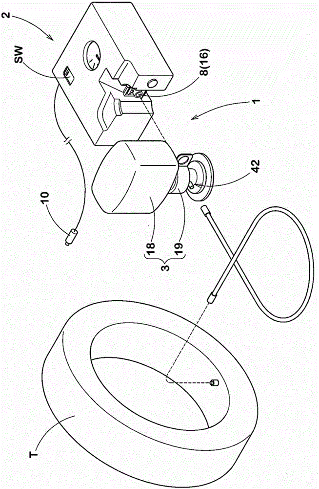
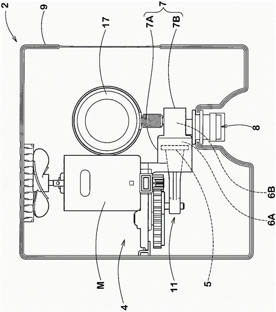
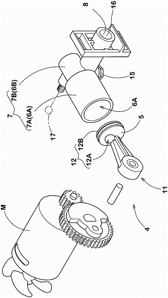
[0056] In order to confirm the effect of the present invention, a trial production was carried out according to the specifications in Table 1. Figure 1 ~ Figure 4 Compressor unit 2 shown. Then, each compressor device 2 is connected to the tire, and when the compressor device 2 is operated, a pressure sensor (different from the pressure gauge 17 ) is used to monitor pressure fluctuations in the shunt chamber 6B. Then, the pressure fluctuation was evaluated based on the difference between the maximum pressure Pmax (pressure when the piston reached the top dead center PU) and the minimum pressure Pmin (pressure when the piston reached the bottom dead center PL) of the split chamber 6B when 15 minutes had elapsed. In addition, the difference (deviation) between the tire internal pressure at the lapse of 15 minutes and the pressure indicated by the pressure gauge 17 was evaluated.

[0057] [Table 1]

[0058]

[0059] As shown in Table 1, it can be confirmed that the pressure ...


PUM


Abstract

The invention provides a tire puncture repair kit which suppress the deviation phenomenon of display pressure without using a chamber. A compressor device 2 and a bottle unit 3 are directly connected. An extraction cap 6 has a one-way valve 37 preventing the back flow of a puncture repair liquid to the inside of the compressor device. The cylinder 7 of the compressor device 2 has a pump chamber 6A and a branch chamber 6B. In the cylinder 7, a ratio between the volume V2 of the pump chamber 6A in the bottom dead point PL and the volume V1 of the pump chamber 6A in the top dead point PU, V2 / V1 is controlled to 7 or lower, and also, the height L1 of the pump chamber 6A in the top dead point PU is controlled to 5.0 mm or higher.

Description

technical field [0001] The invention relates to a tire puncture repair kit, which injects puncture repair fluid and compressed air into a punctured tire in order to perform emergency repairs on the puncture. Background technique [0002] As a stab wound repair kit for emergency repair of stab wounds, it is proposed to use a compressor device that generates compressed air and a bottle unit that contains a bottle container for stab wound repair fluid. A pull-out cap is attached to the mouth (for example, refer to Patent Document 1). In the puncture repair kit described above, the puncture repair fluid is injected into the tire from the bottle unit using compressed air from the compressor unit. After that, the tires are pressurized while visually observing the pressure gauge using the compressed air that is continuously supplied, and after it is confirmed that the desired tire pressure has been achieved, the pressurization is terminated. [0003] In addition, a safety valve i...

Claims


Application Information

Patent Timeline
IPC IPC(8): B29C73/02
Inventor 川谷昭彦河野励周文三
Owner SUMITOMO RUBBER IND LTD
Why Eureka
Eureka Blog
Learn More