
A winged bionic butterfly flapping wing aircraft

A flapping wing aircraft and butterfly technology is applied in the aviation field to achieve the effects of easy installation and disassembly, lightening the weight of the mechanical structure, and realizing human-computer interaction

Inactive Publication Date: 2018-08-10
BEIHANG UNIV
View PDF5 Cites 0 Cited by
  • Summary
  • Abstract
  • Description
  • Claims
  • Application Information

AI Technical Summary

Problems solved by technology

However, attempts to achieve flight using human power by simply vibrating wings have failed

Method used


Image

  • A winged bionic butterfly flapping wing aircraft
  • A winged bionic butterfly flapping wing aircraft
  • A winged bionic butterfly flapping wing aircraft

Examples


Embodiment Construction

[0034] The present invention will be described in further detail below in conjunction with the accompanying drawings.

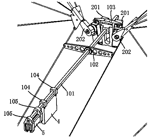
[0035] A winged bionic butterfly flapping aircraft of the present invention comprises a main torso 1, a wing drive assembly 2 and a wing assembly 3, such as figure 1 As shown; wherein, the wing assembly 3 includes a left wing assembly and a right wing assembly, which are installed on the left and right sides of the main body 1 respectively, and are symmetrical in mirror image.

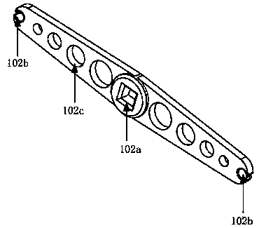
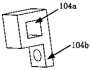
[0036] The main torso 1 includes a main rod 101, a wing connecting hinge 102, a wing-driven servo bracket 103, a controller connecting bracket 104 and a battery connecting bracket 105, such as figure 2 shown. Wherein, the main rod 101 adopts a hollow carbon fiber rod with a cross-section of a square with a side length of 2 mm and a length of 260 mm. The wing drive mounting bracket 103 is a PLA plastic structural part, such as image 3 As shown; the center of the wing driving mount...


PUM


Abstract

The invention discloses a wing-connected butterfly-simulated flapping-wing air vehicle. The wing-connected butterfly-simulated flapping-wing air vehicle comprises a main trunk, wing driving assemblies and wing assemblies, wherein the wing assemblies include a left wing assembly and a right wing assembly which are respectively mounted on the wing driving assemblies on two ends of the front end of the main trunk in a mirror symmetry manner; outer contours of the wing assemblies are fixedly formed through plastic connecting assemblies after being bent by carbon fiber rods so as to form an integral skeleton of the wing-connected butterfly-simulated flapping-wing air vehicle, elastic films are formed through integral cutting according to a wing skeleton and are fixed on the wing skeleton through adhesive tapes to form elastic wings; the wing assemblies are driven through driving steering engines mounted at the front part of the main trunk so as to drive the wings to flap to generate thrust and elevating force for flight, and the pitching and the yawing of a butterfly are realized by independently controlling a starting phase position and an ending phase position of two wings; and by utilizing a micro-control system and a power supply system which are mounted at the rear part of the main trunk, the control and the power supply of the butterfly-simulated flapping-wing air vehicle are realized.

Description

technical field [0001] The invention relates to a bionic robot and a flapping-wing aircraft, belonging to the field of aviation technology. Specifically, it is a flapping wing aircraft that imitates the shape and movement mechanism of Lepidoptera butterflies, which are relatively large winged insects in nature, and is driven by independent servo motors. Background technique [0002] The flapping-wing aircraft has its unique advantages, and has important and extensive applications in the national defense and civil fields. The research on the miniature flapping-wing aircraft has become a hot spot in the field of aviation research. The limitations of early people's understanding of the flapping wing flight method and the limitations of the technological level at that time did not reveal the true veil of this flight method. People in ancient times tried to use various materials to make wings, hoping to fly with birds by relying entirely on human physical strength. Leonardo da ...

Claims


Application Information

Patent Timeline
Patent Type & Authority Patents(China)
IPC IPC(8): B64C33/02
CPCB64C33/02
Inventor 王少萍张益鑫池小楷陈沐桐
Owner BEIHANG UNIV
Learn More