
Automatic loading equipment of non-rotor vulkameter
A technology of automatic feeding and vulcanizer, which is used in instruments, analysis materials, thin material processing, etc., can solve the problems of complex structure of automatic vulcanizers, and achieve the effect of stable transmission, high reliability and precision
- Summary
- Abstract
- Description
- Claims
- Application Information
AI Technical Summary
Problems solved by technology
Method used
Image

Examples
Embodiment Construction
[0024] In order to further understand the features, technical means, and specific goals and functions of the present invention, the present invention will be described in further detail below with reference to the accompanying drawings and specific embodiments.
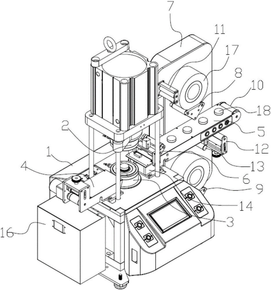
[0025] see figure 1 and Image 6 , The present invention discloses an automatic feeding equipment without rotor vulcanizer, comprising an organic table, an upper mold 2 and a lower mold 3 are arranged on the machine table 1, and the machine table 1 is located on the left side of the lower mold 3 with a Scrap recycling facility 4.
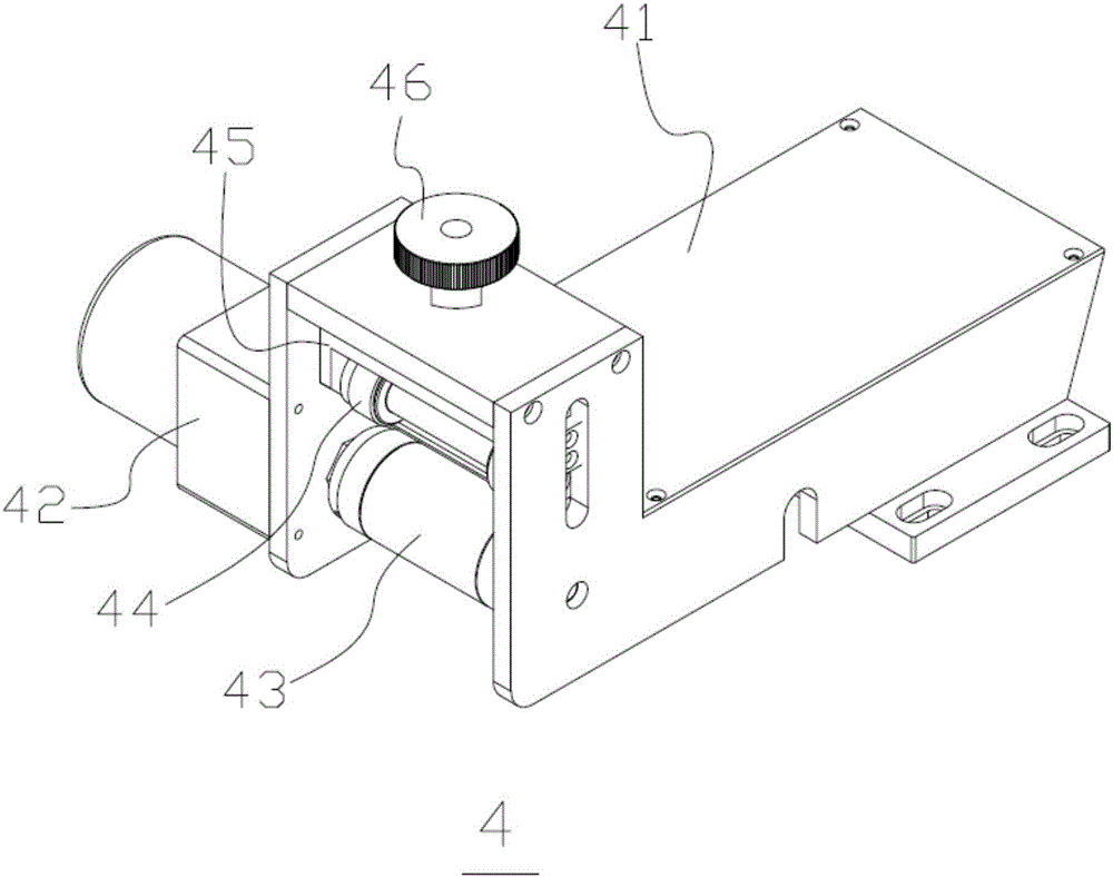
[0026] The waste recycling mechanism 4 includes a bracket seat 41, one end of the bracket seat 41 is connected with the machine table 1, and the other end of the bracket seat 41 is provided with a motor 42 on the outside. The motor 42 is connected with the lower roller 43 in the bracket seat 41. An upper roller 44 is arranged above the lower roller 43, and the upper roller 44 is connected...
PUM
 Abstract
Description
Claims
Application Information